
Fuel distributor working principle and installation requirements
News 2026年 7月 31日 55
A fuel dispenser is one of the most important pieces of equipment in a modern gas station. It is responsible not only for safely and steadily transferring fuel from underground storage tanks to vehicle fuel tanks, but also for accurate fuel measurement, flow control, safety protection, and efficient station management.
To many people, a fuel dispenser may look like a simple machine that delivers fuel. However, behind this simple operation is a highly integrated system that combines:
- Hydraulic fuel delivery technology
- Precision metering systems
- Electronic control systems
- Safety protection devices
All these components work together to ensure a safe, accurate, and efficient refueling process.
This article provides a detailed explanation of:
- The complete fuel flow process inside a fuel dispenser
- Working principles of key components
- Fuel dispenser installation requirements
- Pipeline and electrical installation standards
- Common failures and troubleshooting methods
It is designed to help gas station investors, engineering contractors, maintenance technicians, and fuel equipment buyers better understand modern fuel dispenser systems.
1.Complete Fuel Delivery Process of a Fuel Dispenser
The internal fuel flow path of a fuel dispenser is as follows:
Underground Storage Tank
↓
Double Check Foot Valve
↓
Underground Fuel Pipeline
↓
Filtration System
↓
Self-Priming Fuel Pump
↓
Air Separator
↓
Metering System
↓
Solenoid Valve
↓
Automatic Shut-Off Nozzle
Each component performs a specific function. Together, they complete fuel transportation, pressure control, and accurate fuel measurement.
2.Detailed Working Principle of a Fuel Dispenser
2.1Underground Storage Tank:
The underground storage tank is the fuel storage center of the entire fueling system.
Gasoline or diesel is stored inside the underground tank and then transported through fuel pipelines to the dispenser.
Before installing the fuel dispenser, the storage tank and pipelines must be properly cleaned.
The following contaminants must be removed:
- Welding slag
- Rust particles
- Dust
- Metal debris
These impurities can enter the dispenser system and cause:
- Fuel pump damage
- Solenoid valve blockage
- Flow meter wear
- Nozzle clogging
A clean fuel system is essential for stable operation and longer equipment life.
2.2Double Check Foot Valve
The double check foot valve is installed at the bottom of the fuel suction pipeline inside the underground storage tank.
Its main functions include:
① Preventing Fuel Backflow
When the fuel pump stops working, the valve keeps fuel inside the pipeline and prevents the fuel line from becoming empty.
② Improving Suction Performance
By maintaining fuel inside the pipeline, it reduces air entering the system during startup and improves the self-priming capability of the pump.
③ Preventing Contaminants from Entering the System
It helps prevent sediments at the bottom of the storage tank from entering the fuel delivery system.
Installation Requirement:
The distance between the bottom of the double check foot valve and the bottom of the underground tank should be:
10–15 cm
This prevents the valve from sucking in sediment accumulated at the bottom of the tank.
2.3Underground Fuel Pipeline
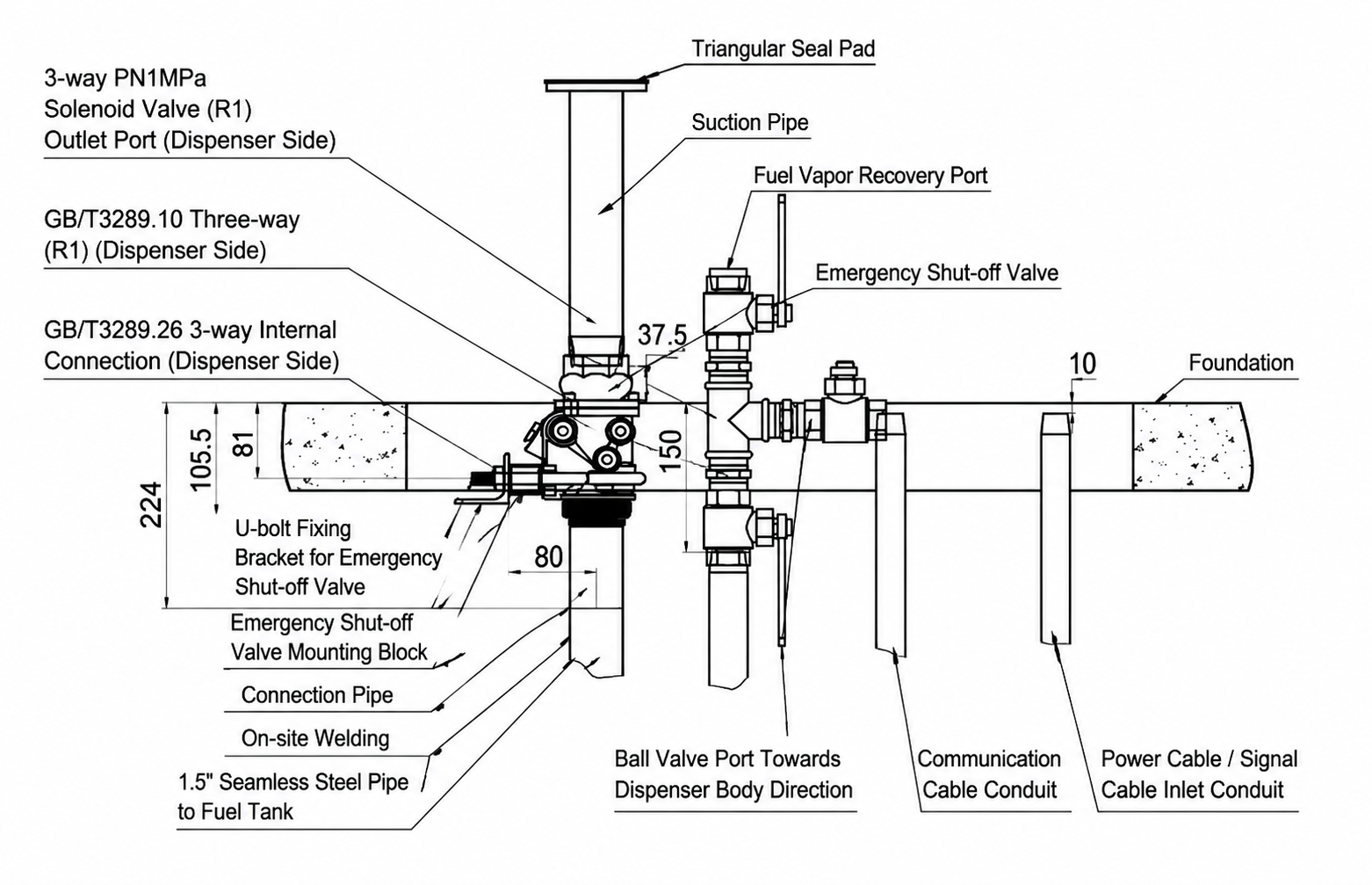
The underground fuel pipeline connects the storage tank with the fuel dispenser.
Recommended pipeline size:
DN40 (1.5 inch)
Pipeline Slope Requirement
The pipeline should maintain an upward slope from the underground tank toward the fuel dispenser:
3/1000 upward slope
Purpose:
- Reduce air accumulation inside the pipeline
- Improve fuel flow stability
- Prevent suction problems
Pipeline Bending Requirements
The number of 90° elbows should be minimized.
Excessive bending increases:
- Fuel flow resistance
- Pump load
- Pressure loss
A smoother pipeline layout improves fuel delivery efficiency.
Installation Distance Requirements
The horizontal distance between the fuel dispenser and underground storage tank is generally:
Approximately 20 m
The vertical distance between the lowest fuel level in the storage tank and the fuel dispenser inlet should be:
No more than 4 m
These requirements help ensure stable suction performance.
3.Working Principle of Main Fuel Dispenser Components
Fuel Filter System:
The fuel filter removes impurities and particles from fuel before it enters the main components.
It protects:
- Fuel pump
- Flow meter
- Solenoid valve
- Fuel nozzle
A blocked filter may cause:
- Reduced fuel flow rate
- Longer refueling time
- Increased pump noise
Maintenance:
The filter element should be inspected and replaced regularly.
3.2 Self-Priming Fuel Pump
The self-priming fuel pump is the power source of the fuel delivery system.
Its main functions are:
- Creating suction pressure
- Transporting fuel from the underground tank to the dispenser
- Maintaining stable fuel flow
If the pump system is installed incorrectly, problems may occur:
- Unable to draw fuel
- Low fuel flow
- Air entering the pipeline
Proper installation and sealing are critical for reliable operation.
3.3 Air Separator
The air separator removes air and vapor from the fuel before measurement.
Its functions include:
- Improving measurement accuracy
- Preventing air from entering the flow meter
- Ensuring accurate fuel sales data
If excessive air enters the fuel system, it may cause:
- Measurement errors
- Unstable fuel flow
- Incorrect transaction data
3.4 Metering System
The metering system is the core component responsible for accurate fuel measurement.
Its function is:
To convert actual fuel flow into accurate sales data.
It directly affects:
- Fuel volume accuracy
- Transaction amount calculation
- Customer trust
- Gas station reputation
A reliable metering system is essential for commercial fueling operations.
3.5 Solenoid Valve
The solenoid valve controls fuel flow ON and OFF.
During Refueling:
The solenoid valve opens, allowing fuel to pass through.
When Refueling Stops:
The solenoid valve closes and stops fuel supply.
Main functions:
- Control fuel flow
- Prevent fuel leakage
- Improve operational safety
3.6 Automatic Shut-Off Nozzle
The automatic shut-off nozzle is the final control device before fuel enters the vehicle tank.
Its main function:
When the vehicle fuel tank reaches full capacity, the nozzle automatically stops fuel delivery.
This prevents:
- Fuel overflow
- Fuel waste
- Safety hazards
4.Fuel Dispenser Installation Technical Requirements
Proper installation is essential for ensuring the safety, accuracy, and long-term reliability of a fuel dispenser system.
The installation process must comply with relevant fuel station construction standards and explosion-proof requirements.
4.1 Installation Location Requirements
The installation of fuel distributors must comply with local regulations.
Installation Environment Requirements:
The installation area should:
- Have a protective canopy against rain and sunlight
- Avoid long-term exposure to harsh weather conditions
- Meet hazardous area and explosion-proof requirements
A suitable installation environment helps protect electrical components and extend equipment service life.
4.2 Foundation Installation Requirements
The fuel dispenser base must be installed on:
A dedicated concrete foundation
The fixing methods include:
- Anchor bolts
- Expansion bolts
The foundation should reserve openings for:
- DN40 fuel inlet pipe
- Power cable routing
- Grounding wire connection
After installation:
All remaining gaps and openings should be properly sealed and filled with yellow sand.
This prevents external damage and improves installation stability.
4.3 Fuel Pipeline Installation Requirements
Before connecting the fuel dispenser:
The underground storage tank and pipeline system must be thoroughly cleaned.
Remove:
- Welding slag
- Rust
- Metal particles
- Other contaminants
These contaminants may damage:
- Fuel pumps
- Flow meters
- Solenoid valves
Pipeline Pressure Test Requirement
Before commissioning:
The pipeline system must undergo a pressure test.
Test pressure:
0.5 MPa
The system must confirm:
- No fuel leakage
- Sufficient pipeline strength
- Reliable connections
Only after passing the test can the fuel dispenser be connected and operated.
5.Electrical Installation Requirements for Fuel Dispensers
Electrical installation is one of the most important safety aspects of a fuel dispenser system.
Because fuel stations contain flammable gases and vapors, all electrical work must meet explosion-proof requirements.
5.1Grounding Requirements
To ensure equipment safety:
The fuel dispenser must have proper grounding and lightning protection.
Lightning Protection Ground:
Grounding resistance:
≤10Ω
Safety Protection Ground:
Grounding resistance:
≤3Ω
Safety Grounding Wire:
Specification:
1×15mm² insulated copper wire
Important Notice:
The lightning protection grounding system must not be connected to the safety protection grounding system.
Separate grounding systems must be maintained to ensure electrical safety.
5.2 Power Supply Connection Requirements
The fuel dispenser power supply should use:
TN-S power supply system
Recommended power supply:
Three-phase four-wire 380V power supply
Each fuel dispenser must have:
- An independent control switch
- Independent power protection
This improves maintenance safety and prevents electrical failures from affecting multiple dispensers.
5.3 Cable Requirements
The power cable should use:
RVV oil-resistant insulated cable
Recommended user power cable specification:
5×2.5mm²
During installation, pay attention to:
- Cable outer diameter must match the explosion-proof junction box
- Sealing gasket must not be omitted
- Metal sealing washer must be installed correctly
- Compression nut must be tightened to ensure sealing performance
Incorrect cable installation may affect the explosion-proof performance of the equipment.
6. Fuel Dispenser Installation Safety Requirements
Electrical installations must comply with local regulations.
During installation and maintenance:
- Do not open explosion-proof electrical boxes while powered
- Restore all sealing components after wiring
- Ensure explosion-proof performance remains intact
Failure to follow these requirements may create serious safety risks.
6.1 Pipeline Cleaning Requirements
Before installation:
The fuel system must be cleaned completely.
Remove:
- Welding slag
- Iron filings
- Foreign particles
Otherwise, contaminants may damage:
- Fuel pump
- Flow meter
- Solenoid valve
A clean pipeline system is the foundation of reliable fuel dispenser operation.
7. Common Fuel Dispenser Problems and Solutions
Problem 1: Fuel Dispenser Cannot Pump Fuel
Possible Causes:
① Air entering the pipeline
② Damaged double check foot valve
③ Blocked fuel pipeline
Solutions:
- Check pipeline sealing condition
- Inspect and replace the foot valve if necessary
- Clean the fuel pipeline
Problem 2: Slow Fuel Flow During Refueling
Possible Causes:
- Clogged fuel filter
- Worn fuel pump
- Excessive pipeline resistance
Solutions:
- Clean or replace the filter element
- Check fuel pump operating condition
- Inspect pipeline layout and resistance
Problem 3: Inaccurate Fuel Measurement
Possible Causes:
- Flow meter wear
- Air separator malfunction
- Air entering the fuel system
Solutions:
- Check air separator operation
- Inspect the metering system
- Perform calibration if required
Accurate measurement is essential for maintaining customer trust and preventing financial losses.
Problem 4: Fuel Leakage
Possible Causes:
- Damaged seals
- Loose connections
- Aging pipelines
Solutions:
Stop using the equipment immediately.
Check:
- Sealing components
- Pipeline connections
- Threaded joints
Replace damaged parts before restarting operation.
Fuel leakage is a serious safety issue and should never be ignored.
8. Daily Fuel Dispenser Maintenance Recommendations
Regular inspection helps maintain safe and stable operation.
Recommended inspection items:
✓ Check pipelines for fuel leakage
✓ Check whether connections are loose
✓ Inspect filter condition
✓ Listen for abnormal pump noise
✓ Verify fuel measurement accuracy
✓ Check grounding system performance
Keep Equipment in Good Condition:
- Keep the dispenser clean
- Protect electrical components from moisture
- Ensure explosion-proof parts remain complete
- Replace damaged components promptly
Proper maintenance can significantly extend equipment lifespan and reduce unexpected downtime.
Conclusion
A fuel dispenser is not simply a device that delivers fuel. It is a complete energy equipment system integrating:
- Hydraulic fuel transportation
- Precision measurement technology
- Automatic control systems
- Explosion-proof safety protection
From the underground storage tank to the automatic shut-off nozzle, every component plays an important role in fuel station efficiency and safety.
Correct installation, professional commissioning, and regular maintenance are the keys to ensuring long-term stable operation.
For gas station investors, engineering contractors, and fuel equipment buyers, understanding the working principle and installation requirements of fuel dispensers can help:
- Reduce operational risks
- Improve project quality
- Increase equipment reliability
- Build safer and more efficient fueling stations
A well-designed and properly installed fuel dispenser system is the foundation of a modern, reliable, and high-performance gas station.