
Gas Station Tank Manhole: Structure, Installation Requirements and Key Data
News 2026年 8月 13日 52
Introduction
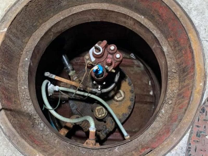
A tank manhole is an important part of an underground fuel storage system.
Located above the underground fuel tank, the tank manhole provides an access and operating space for equipment such as:
- Submersible oil pumps
- Fuel piping connections
- Liquid level sensors
- Leak detection equipment
- Vapor recovery connections
- Other tank accessories
According to GB 50156-2021 — Technical Standard for Automobile Gas Filling Stations, CNG/LNG Stations and Hydrogen Refueling Stations, buried fuel tanks should be provided with manholes and operation wells.
When a tank manhole is located beneath a vehicle traffic area, a dedicated sealed manhole cover and frame for gas station traffic areas should be used.
Therefore, the basic concept is simple:
The underground tank stores the fuel, while the tank manhole provides access for equipment installation, connection, inspection, and maintenance.
1. What Is a Gas Station Tank Manhole?
A gas station tank manhole is an operating space installed above an underground fuel tank.
It provides access to equipment connected to the tank and allows technicians to perform installation, inspection, and maintenance.
A typical system can be simplified as:
              Fuel Dispenser
                    ↑
                    │
             Underground
              Fuel Pipe
                    ↑
                    │
           Submersible oil pump
                    ↑
             Tank Manhole
                    ↑
                    │
          Underground Fuel Tank
The tank manhole is therefore an important connection area between the underground fuel storage system and the fuel dispensing system.
2. What Equipment Is Installed in a Tank Manhole?
The exact configuration depends on the tank design, fuel system, vapor recovery system, and local regulations.
Typical equipment may include:
| Equipment | Main Function |
|---|---|
| Submersible oil pump | Transfers fuel to the dispenser |
| Product Outlet Pipe | Connects the tank to underground fuel piping |
| Fill Pipe | Connects the tank to the fuel unloading system |
| Liquid Level Sensor | Measures fuel level |
| Leak Detection System | Monitors potential tank leakage |
| Vapor Recovery Pipe | Transfers recovered fuel vapor |
| Tank Gauging Port | Allows manual or automatic tank level measurement |
GB 50156-2021 specifies that the fuel inlet connection, fuel outlet connection, or Submersible oil pump installation opening should be located on the tank manhole cover.
This means the manhole cover is not simply a protective cover. It is also an important equipment mounting and connection platform.
3. Key Tank Manhole Data at a Glance
For engineers, contractors, and equipment buyers, the following data are particularly useful.
| Item | Key Requirement / Reference |
|---|---|
| Tank cover depth in non-traffic areas | ≥ 0.5 m |
| Tank top depth below concrete pavement in traffic areas | Recommended ≥ 0.9 m |
| Backfill around steel tank | ≥ 0.3 m |
| Double-wall tank leak detection riser diameter | Recommended 80 mm |
| Leak detection riser wall thickness | Not less than 4 mm recommended |
| Fill pipe distance from tank bottom | 50–100 mm |
| Submersible oil pump inlet above tank bottom | 150–200 mm |
| Tank gauging pipe distance from tank bottom | Approximately 200 mm |
| High-level alarm | 90% |
| Automatic filling shutoff | 95% |
| Leak detection resolution for single-wall tanks | Not greater than 0.8 L/h recommended |
Note: Terms such as “shall,” “should,” “recommended,” and “not less than” have different meanings in technical standards. Actual projects should follow the current local regulations, approved design documents, and equipment manufacturer’s installation requirements.
4. How Deep Should an Underground Fuel Tank Be Buried?
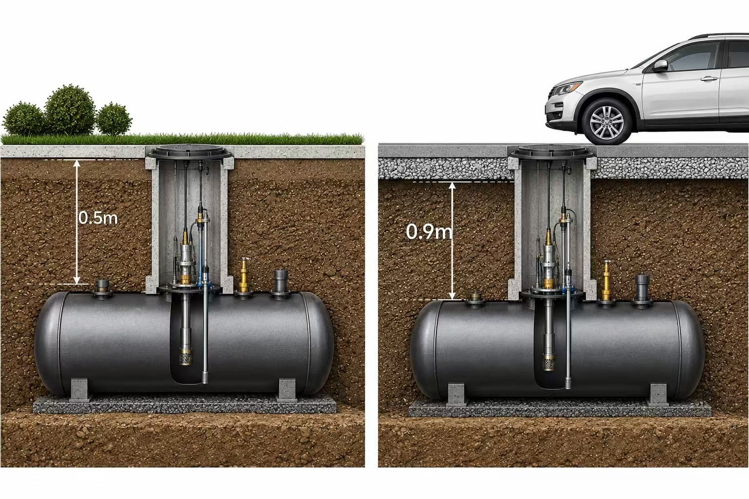
Tank burial depth is one of the most common questions in underground fuel storage projects.
According to GB 50156-2021:
Non-Traffic Areas
The soil cover above the top of the underground tank should be:
≥ 0.5 m
Vehicle Traffic Areas
The top of the tank should generally be:
≥ 0.9 m below the concrete pavement
For steel tanks, the surrounding backfill should also use suitable neutral sand or fine soil, with a thickness of:
≥ 0.3 m
A simplified illustration:
Non-Traffic Area

Ground Surface
────────────────────
       ↓ ≥ 0.5 m
────────────────────
     Underground
      Fuel Tank


Vehicle Traffic Area

Concrete Pavement
════════════════════
       ↓ ≥ 0.9 m
════════════════════
     Underground
      Fuel Tank
The actual burial depth should also consider the tank structure, traffic loading, groundwater conditions, foundation design, and local construction requirements.
5. Double-Wall Fuel Tank Leak Detection
Double-wall underground tanks provide an additional monitoring space between the inner and outer tank walls.
A simplified structure is:
        Leak Detection Riser
                 │
                 ↓
        ┌─────────────────┐
        │    Outer Tank   │
        │   ┌─────────┐   │
        │   │ Inner   │   │
        │   │  Tank   │   │
        │   │  Fuel   │   │
        │   └─────────┘   │
        │ Leak Monitoring │
        │      Space      │
        └─────────────────┘
For applicable double-wall tank structures, GB 50156-2021 requires a leak detection riser.
Key reference data include:
- Recommended diameter: 80 mm
- Recommended wall thickness: ≥ 4 mm
- Installed on the longitudinal centerline of the tank top
- Connected to the interstitial space between the inner and outer tanks
- Designed to allow manual or online leak monitoring
This allows potential leakage from the inner tank to be detected before it reaches the surrounding soil.
6. Where Is the Submersible oil pump Installed?
The relationship between the tank manhole and Submersible oil pump is particularly important.
GB 50156-2021 specifies that the fuel inlet connection, fuel outlet connection, or Submersible oil pump installation opening should be located on the tank manhole cover.
For a typical pressure fuel system:
          Fuel Dispenser
                 ↑
                 │
          Fuel Pipeline
                 ↑
                 │
        Submersible oil pump
                 ↑
           Tank Manhole
                 ↑
                 │
        Underground Tank
The Submersible oil pump is installed inside the tank, while the pump head and connection components are accessible from the tank top.
According to the standard, the Submersible oil pump inlet should be 150–200 mm above the tank bottom.
         Submersible oil pump
                  │
                  ↓
             Pump Inlet
                  │
                  │ 150–200 mm
                  ↓
──────────────────────────
        Tank Bottom
──────────────────────────
This dimension is important when selecting and installing the pump assembly.
7. What Is the Required Fill Pipe Height?
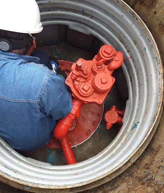
The fuel fill pipe is another important component installed through the tank manhole area.
According to GB 50156-2021, the fill pipe should extend to approximately:
50–100 mm above the tank bottom.
The lower end of the fill pipe should use a suitable configuration, such as a 45° angled opening or T-shaped opening, according to the standard and project design.
Simplified arrangement:
           Fill Pipe
               │
               │
               ↓
              45°
                \
                 \
                  ↓
────────────────────────
       50–100 mm
────────────────────────
        Tank Bottom
The purpose is to control the incoming fuel flow and reduce unnecessary turbulence and splashing inside the tank.
8. Why Is Tank Manhole Piping Layout Important?
The space inside a tank manhole is limited.
Therefore, pipes and equipment cannot simply be installed wherever there is available space.
GB 50156-2021 requires the piping and equipment inside the tank manhole to be arranged so that the tank manhole cover can be removed.
This is an important maintenance requirement.
Poor Layout
Pipes + Valves + Pump
     crowded together

          ↓

Manhole Cover
cannot be removed easily
Better Layout
        Manhole Cover
              ↓
       Can be removed
              ↓
       Pump accessible
              ↓
      Pipe connections
        can be serviced
When designing a tank manhole, engineers should consider not only installation space, but also:
- Pump removal space
- Tool access
- Pipe connection access
- Sensor maintenance
- Future equipment replacement
9. How Is the Manhole Connected to External Fuel Piping?
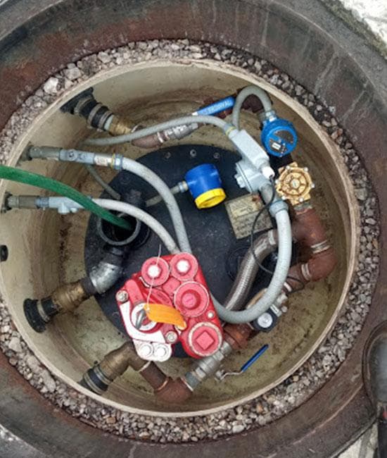
The tank manhole connects the tank-side piping to the underground fuel piping leading to the dispenser.
GB 50156-2021 recommends using a metal flexible connection between the connection pipe on the manhole cover and the external pipeline.
Typical arrangement:
Underground Fuel Tank
          ↓
     Manhole Cover
          ↓
     Tank Connection
          ↓
   Metal Flexible Joint
          ↓
 Underground Fuel Pipe
          ↓
     Fuel Dispenser
The flexible connection can help accommodate installation tolerances and certain movement between connected components.
The final connection type should be selected according to the piping material, pipe diameter, connection standard, project design, and manufacturer’s requirements.
10. What If the Tank Manhole Is Under a Vehicle Lane?
If the tank manhole is located in a vehicle traffic area, three issues are particularly important.
1. Manhole Cover
Use a:
Dedicated sealed manhole cover and frame designed for gas station traffic areas.
2. Tank Burial Depth
The top of the underground tank should generally be:
≥ 0.9 m below concrete pavement
3. Sealing and Water Protection
The manhole system should provide appropriate protection against:
- Rainwater
- Groundwater
- Dust
- Mechanical impact
The standard’s technical explanation indicates that dedicated sealed covers and frames in vehicle traffic areas are intended to provide protection against water and dust and help avoid sparks caused by impact.
Therefore, an ordinary utility manhole cover should not automatically be considered suitable for a gas station fuel tank manhole.
11. Two Important Tank Filling Safety Levels
The tank manhole system is also associated with the tank gauging and overfill protection system.
According to GB 50156-2021:
At 90% Tank Capacity
A:
High-level alarm
should be triggered.
At 95% Tank Capacity
The system should:
Automatically stop further fuel filling.
Simplified:
100% ───────── Maximum Tank Capacity

 95% ───────── Automatic Filling Shutoff

 90% ───────── High-Level Alarm

  0% ───────── Tank Bottom
These two numbers are particularly important when selecting the tank gauging and overfill protection system.
12. Tank Manhole Installation Checklist
Before installing a tank manhole, contractors and buyers should check:
| Check Item | Key Requirement |
|---|---|
| Operation well | Required for buried tank manholes |
| Traffic-area cover | Dedicated sealed cover and frame |
| Non-traffic tank cover depth | ≥ 0.5 m |
| Traffic-area tank depth | Recommended ≥ 0.9 m |
| Steel tank backfill | ≥ 0.3 m |
| Leak detection riser | Recommended 80 mm |
| Leak detection riser wall | ≥ 4 mm recommended |
| Fill pipe distance from bottom | 50–100 mm |
| Pump inlet height | 150–200 mm |
| Manhole piping | Must allow cover removal |
| External pipe connection | Metal flexible connection recommended |
| High-level alarm | 90% |
| Automatic filling shutoff | 95% |
13. How to Choose a Tank Manhole
When purchasing a tank manhole, price should not be the only consideration.
Check these five points first.
1. Tank Compatibility
Confirm:
- Tank capacity
- Tank diameter
- Tank material
- Manhole opening dimensions
2. Submersible oil pump Compatibility
Confirm:
- Mounting dimensions
- Flange
- Pump head dimensions
- Product outlet
- Electrical connection
3. Piping Compatibility
Confirm:
- Product pipe size
- Fill pipe
- Vapor recovery connection
- Vent connection
- Number of outlets
4. Installation Environment
Determine whether the manhole is installed:
- In a non-traffic area
- Under a vehicle lane
- In a high-groundwater area
- In a heavy-rainfall region
5. Maintenance Access
Always confirm:
Can the manhole cover be removed?
Can the Submersible oil pump be removed?
Can the pipe connections be accessed?
A good manhole design should make both installation and future maintenance easier.
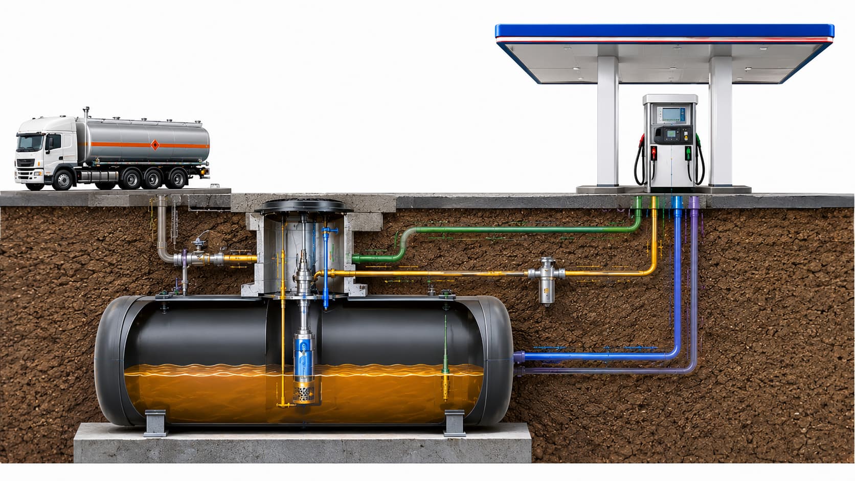
14. How Does the Tank Manhole Connect the Complete Underground System?
The tank manhole is only one component of the underground fuel system, but it connects several critical systems.
                    Fuel Dispenser
                          ↑
                          │
                   Fuel Pipeline
                          ↑
                          │
                  Submersible oil pump
                          ↑
                  ┌───────┴───────┐
                  │  Tank Manhole │
                  └───────┬───────┘
                          │
                   Underground Tank
                          │
              ┌───────────┴───────────┐
              │                       │
        Tank Monitoring         Vapor Recovery
              │                       │
              └───────────┬───────────┘
                          │
                   Safety Monitoring
This is why the:
fuel tank + tank manhole + Submersible oil pump+ piping + fuel dispenser
should be considered as one complete system rather than as completely independent products.
Conclusion
A tank manhole is much more than an underground cover. It is a critical operating and connection area within a gas station’s underground fuel storage system.
Some key GB 50156-2021 figures to remember are:
0.5 m — minimum soil cover above the tank in non-traffic areas
0.9 m — recommended tank depth below concrete pavement in traffic areas
0.3 m — minimum backfill thickness around a steel tank
80 mm / 4 mm — recommended leak detection riser diameter and wall thickness for applicable double-wall tanks
150–200 mm — Submersible oil pump inlet above the tank bottom
50–100 mm — fill pipe distance from the tank bottom
90% / 95% — high-level alarm / automatic filling shutoff
These figures provide useful reference points when designing or purchasing a tank manhole, underground fuel tank, Submersible oil pump, and associated piping system.
Actual projects should always comply with the current regulations, approved engineering design, local fire-safety requirements, and equipment manufacturer’s installation instructions.
FAQ
What is a gas station tank manhole?
A tank manhole is an operating and access space installed above an underground fuel tank. It provides access to equipment such as Submersible oil pumps, piping connections, liquid level sensors, and leak detection equipment.
Is a tank manhole the same as a fuel dispenser island?
No.
The tank manhole is located above the underground fuel tank and belongs to the underground storage system. The fuel dispenser is located in the vehicle refueling area and dispenses fuel to vehicles.
Does every tank manhole contain a Submersible oil pump?
Not necessarily.
It depends on the station’s fuel delivery system. In a pressure fuel system using a Submersible oil pump, the pump is normally installed through the top of the underground tank.
Can a tank manhole be installed under a vehicle lane?
Yes, but additional requirements apply.
The design must consider vehicle loading, sealing, water protection, and tank burial depth. A dedicated sealed manhole cover and frame should be used for gas station traffic areas.
How far above the tank bottom should the Submersible oil pump inlet be?
According to GB 50156-2021, the Submersible oil pump inlet should be 150–200 mm above the tank bottom.
How deep should an underground fuel tank be buried?
For non-traffic areas, the soil cover above the tank should generally be at least 0.5 m.
For vehicle traffic areas, the tank top should generally be at least 0.9 m below the concrete pavement.
Why is maintenance space important?
Submersible oil pumps, sensors, valves, and piping components may need to be inspected, repaired, or replaced during the service life of the gas station. The manhole should therefore be designed to allow these components to be accessed and removed safely.