
Submersible oil Pump: Installation, Wiring, Troubleshooting & Maintenance
News 2026年 8月 6日 87
A reliable fuel dispensing system depends on the stability and performance of every component, especially the submersible oil pump installed inside the underground storage tank.
As the core power unit of modern fuel stations, the Submersible oil pump is responsible for transferring fuel from the underground tank to the dispenser through the pipeline system. Correct installation, proper electrical wiring, regular inspection and professional maintenance are essential to ensure safe operation, stable fuel flow and long service life.
For fuel station contractors, operators and equipment suppliers, understanding the installation requirements and troubleshooting methods of Submersible oil pump can effectively reduce downtime, avoid unnecessary repair costs and improve overall station efficiency.
This guide provides a complete overview of:
- Submersible fuel pump installation preparation
- Required installation accessories
- Mechanical installation requirements
- Electrical wiring procedures
- PMA motor inspection methods
- Overline bridge component replacement
- Common pump failures and solutions
- Daily maintenance recommendations
- Preparation Before submersible oil pump Installation
Before installing the submersible oil pump, the installation environment, underground tank condition and electrical system must be carefully checked.
A professional installation process helps prevent problems such as:
- Motor failure
- Poor fuel delivery
- Electrical short circuits
- Leakage risks
- Difficult future maintenance
Before installation, make sure all required components and tools are prepared.
Recommended Installation Accessories
The main installation accessories include:
- Riser pipe flange
- Flexible outlet hose
- Outlet ball valve (optional)
- Flange gasket
- Explosion-proof flexible conduit
- Explosion-proof sealing components
These accessories ensure a secure connection between the pump, fuel pipeline and electrical system.
- Riser Pipe, Outlet Connection and Wiring Requirements
Riser Pipe Installation Requirements
The supporting riser pipe should use:
Ø114 seamless steel pipe
with:
- NPT external thread connection
- Minimum recommended height: 300mm
The threaded connection must use sealing compound to ensure:
- Reliable sealing
- Electrical grounding continuity
- Prevention of fuel vapor leakage
The riser pipe must be installed vertically to ensure stable operation of the submersible oil pump
Outlet Hose Installation Requirements
The pump outlet can use:
DN50 corrugated flexible hose
Connection specifications:
- One side: 2-inch NPT external thread connected to pump outlet
- Other side: connected to pipeline flange
Recommended hose length:
300–500mm
The actual length depends on the site installation conditions.
Threaded connections must use sealing compound to ensure proper grounding and sealing performance.
Mechanical Installation Requirements
Before placing the submersible oil pump motor into the underground tank:
- Remove all welding slag from the connection area between the riser pipe and large flange.
- Prevent sharp metal debris from damaging the motor.
Installation requirements:
Motor bottom clearance:
The distance between the pump motor bottom and tank bottom should be:
150–200mm
This prevents:
- Sediment entering the pump
- Damage caused by tank bottom contact
- Reduced pump performance
Vertical Installation Requirement
The submersible oil pump must be installed:
Perpendicular to the large flange cover
A tilted installation may cause:
- Uneven motor operation
- Increased vibration
- Shortened service life
- Electrical Wiring Requirements
Correct wiring is critical for safe and stable operation.
Power Cable Requirements
For constant-speed pumps:
Recommended cable specification:
RVV 3 × 2.5mm² or above
The cable must meet:
- Voltage requirements
- Current capacity requirements
- Explosion-proof installation standards
Control Cabinet Wiring
The output cable from the submersible oil pump control cabinet passes through:
3/4-inch cable entry hole
and enters the capacitor connection chamber.
The wiring connection:
| Control Cabinet Wire | Pump Connection |
|---|---|
| Live wire | Black wire |
| Neutral wire | Orange wire |
| Ground wire | Pump head grounding terminal |
Always confirm wiring according to the actual pump model.
Thermal Overload Protection Adjustment
The thermal overload protector in the control cabinet should be adjusted to approximately:
10A
Correct adjustment helps protect the motor from:
- Overcurrent
- Overload
- Abnormal operation
Important Safety Requirement
Never test the submersible oil pump when the underground tank is empty.
Operating the pump without fuel for a long time may cause:
- Motor overload protection activation
- Impeller sticking
- Permanent motor damage
- PMA Motor Electrical Inspection and Testing
Before connecting power to the submersible oil pump, the motor electrical condition must be carefully inspected.
A proper electrical test can help identify insulation problems, wiring errors and potential motor failures before the pump starts operating.
Motor Insulation Resistance Test
Before measuring insulation resistance:
Disconnect the following motor wires from the capacitor:
- Red wire
- Black wire
- Orange wire
Use a multimeter with:
MΩ measurement range
Measure the resistance between:
- Each motor wire
- Pump head grounding point
The insulation resistance requirement:
The resistance value must be higher than 20 MΩ
If the measured value is lower than 20 MΩ, it indicates:
- Poor insulation performance
- Possible leakage risk
- Potential motor damage
The insulation test should always be completed before the first startup or after long-term storage.
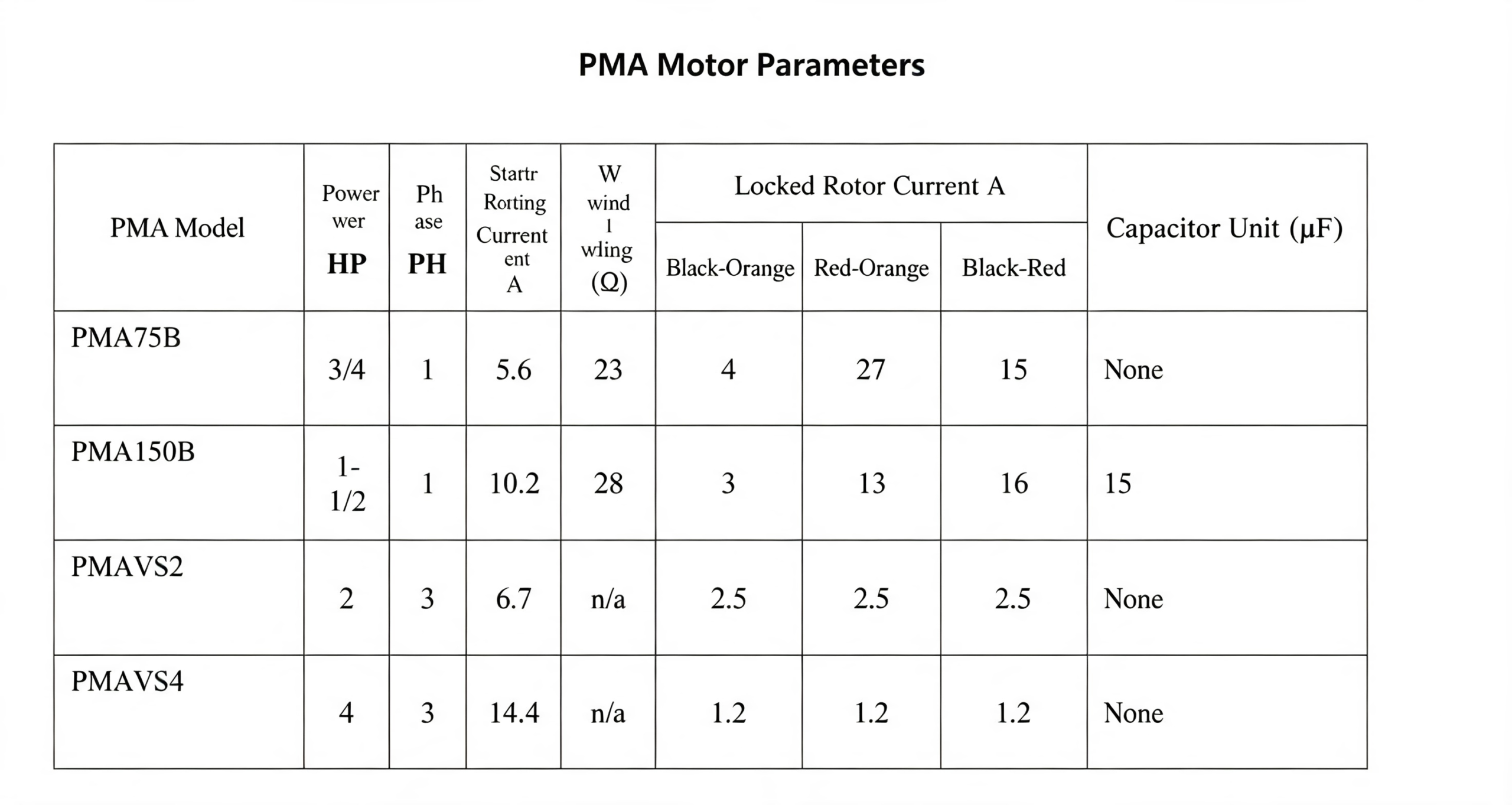
Capacitor Wiring Inspection
Incorrect capacitor wiring may cause:
- Motor failure to start
- Incorrect motor rotation direction
- Abnormal pump operation
Before powering the system:
Always confirm:
- Capacitor connection
- Wire color matching
- Motor terminal connection
A wrong connection may cause the pump to run incorrectly and affect fuel delivery performance.
- Complete submersible oil pump Wiring Requirements
Correct electrical wiring is essential for safe and stable operation.
The wiring process should follow the equipment specifications and local electrical safety standards.
Cable Entry Connection
The output cable from the submersible oil pump control cabinet should pass through:
3/4-inch cable entry hole
into:
the capacitor connection chamber
Make sure:
- Cable sealing is properly installed
- Cable protection is complete
- Explosion-proof requirements are satisfied
Power Cable Connection
The control cabinet output wires should be connected as follows:
| Control Cabinet Output | Pump Connection |
|---|---|
| Live wire | Black wire |
| Neutral wire | Orange wire |
| Ground wire | Pump head grounding terminal |
The grounding connection must be reliable to ensure electrical safety.
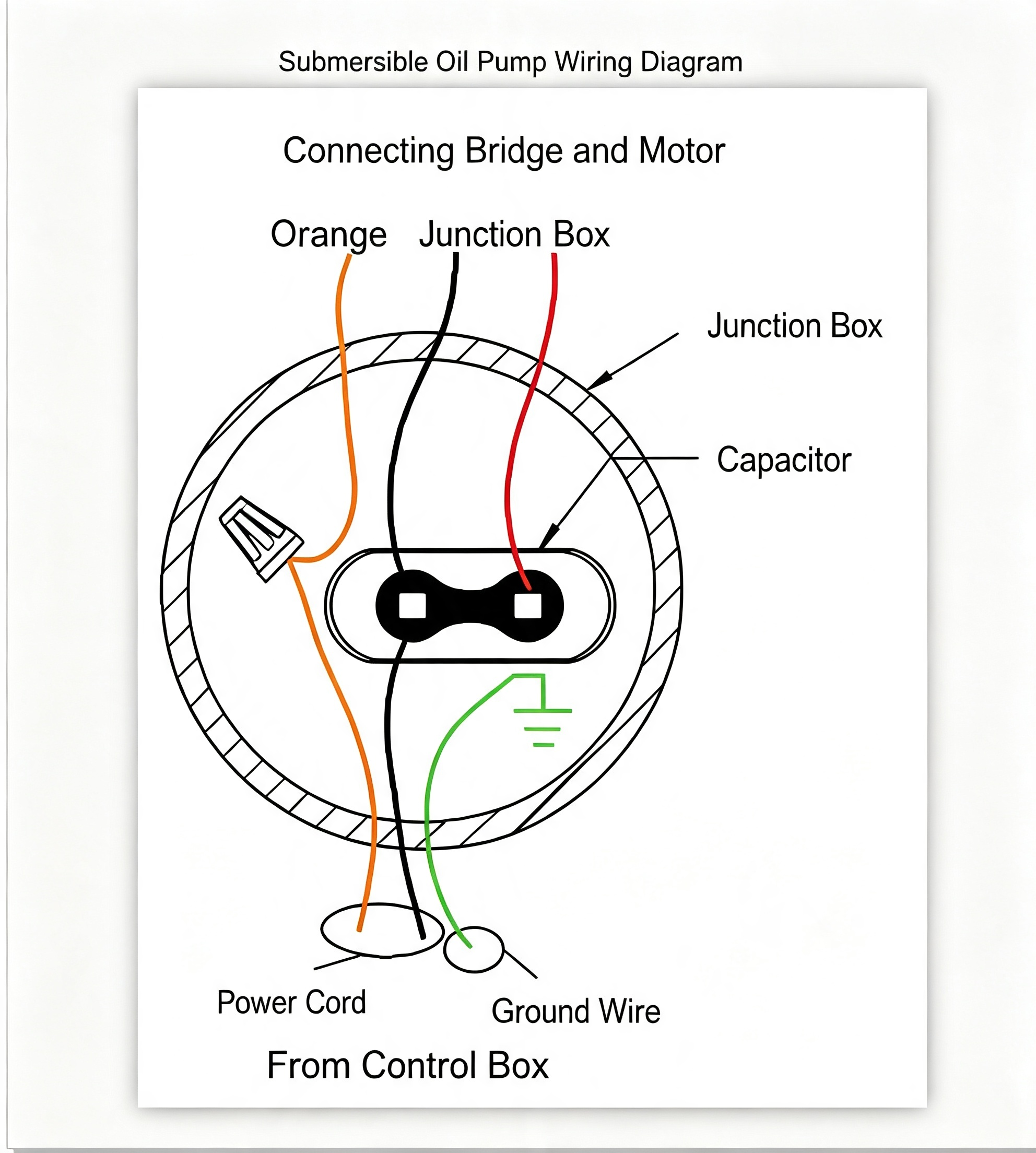
Thermal Overload Protection Adjustment
The thermal overload protector inside the control cabinet should be adjusted to approximately:
10A
Correct overload protection helps prevent:
- Motor overheating
- Excessive current damage
- Long-term electrical stress
Fuel Dispenser Signal Inspection
After installation:
Check that the fuel dispenser nozzle signal correctly controls the corresponding submersible oil pump circuit.
The system should ensure:
When the dispenser nozzle is lifted:
→ The correct pump starts.
When dispensing stops:
→ The pump stops normally.
Incorrect signal wiring may cause:
- Pump unable to start
- Wrong pump operation
- Control system failure
Never Operate Pump Without Fuel
The submersible oil pump must never be tested for a long time when the underground tank is empty.
Running without fuel may cause:
- Motor overheating
- Thermal overload protection activation
- Impeller sticking
- Permanent motor damage
Fuel inside the tank provides:
- Cooling effect
- Lubrication
- Stable motor operation
Restart Procedure After Long-Term Storage
If the submersible oil pump has been installed in an empty tank and unused for:
More than 3 months
Before restarting:
- Remove the motor filter cover
- Manually rotate the motor
- Confirm smooth rotation
- Restore power supply
This prevents:
- Motor seizure caused by rust
- Startup failure
- Mechanical damage
- Overline Bridge Component Structure and Replacement Guide
The overline bridge component is an important electrical isolation part inside the submersible oil pump system.
It functions as:
- Electrical connection bridge
- Explosion-proof isolation component
- Power transmission connector
- Safety separation device
It connects:
Power connection chamber
and
Motor connection chamber
Under normal operation:
The component transfers electrical power from the supply side to the motor.
During maintenance:
It allows technicians to disconnect the motor power connection safely.
Why Overline Bridge Replacement May Be Required
Because the submersible oil pump operates underground for long periods, it is exposed to:
- Moisture
- Fuel vapor
- Corrosion
- Voltage fluctuations
- Continuous operation stress
During:
- Gas station renovation
- Tank cleaning
- Pump removal and installation
Improper handling may cause:
- Bent connector pins
- Poor electrical contact
- Reduced insulation performance
- Pump operation failure
Therefore, replacement of the overline bridge assembly may be required when damage occurs.
Important Safety Warning
Before any maintenance operation:
Turn off the power supply completely.
Do not rely on the overline bridge component to disconnect the STP power supply.
The overline bridge only disconnects:
Motor power connection
It does not guarantee that all electrical wiring inside the connection chamber is completely de-energized.
Always verify power isolation before maintenance.
- Overline Bridge Component Removal and Installation Procedure
The overline bridge assembly is a precision electrical connection component. Any maintenance or replacement work must be performed carefully according to the correct procedure.
Before starting any operation:
Turn off the submersible oil pump power supply completely.
Make sure the power cannot be accidentally restored during maintenance.
Recommended safety steps:
- Switch off the power at the control cabinet
- Mark the power switch as “Maintenance in Progress – Do Not Switch On”
- Confirm that the circuit is completely de-energized
Removing the Overline Bridge Assembly and Male Connector
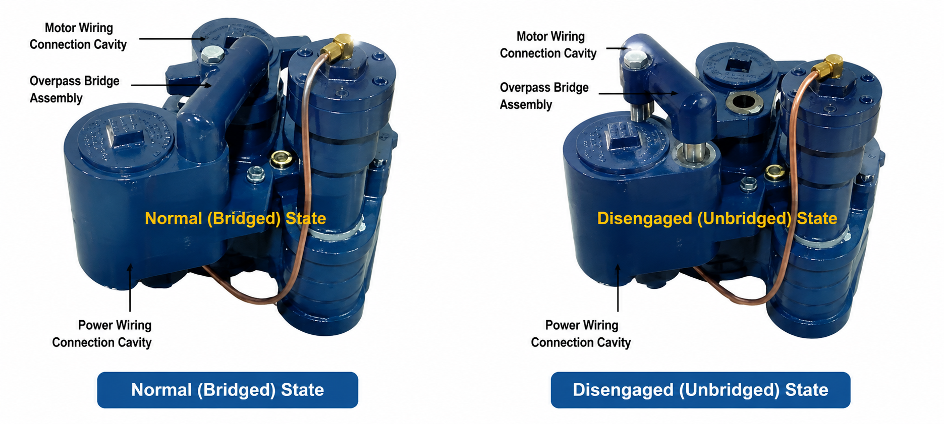
Follow these steps for removal:
Step 1: Disconnect Power Supply
At the power supply cabinet:
- Turn off the submersible oil pump power
- Lock or mark the power switch to prevent accidental operation
Step 2: Loosen the Overline Bridge Fixing Bolt
Slowly loosen the:
Hexagon fixing bolt
until the overline bridge assembly becomes loose.
Do not forcefully pull the component to avoid damaging the connector.
Step 3: Remove Connection Chamber Components
Remove:
- Connection chamber cover
- Capacitor (if installed)
Then disconnect:
- Wire connector connection from the overline bridge assembly
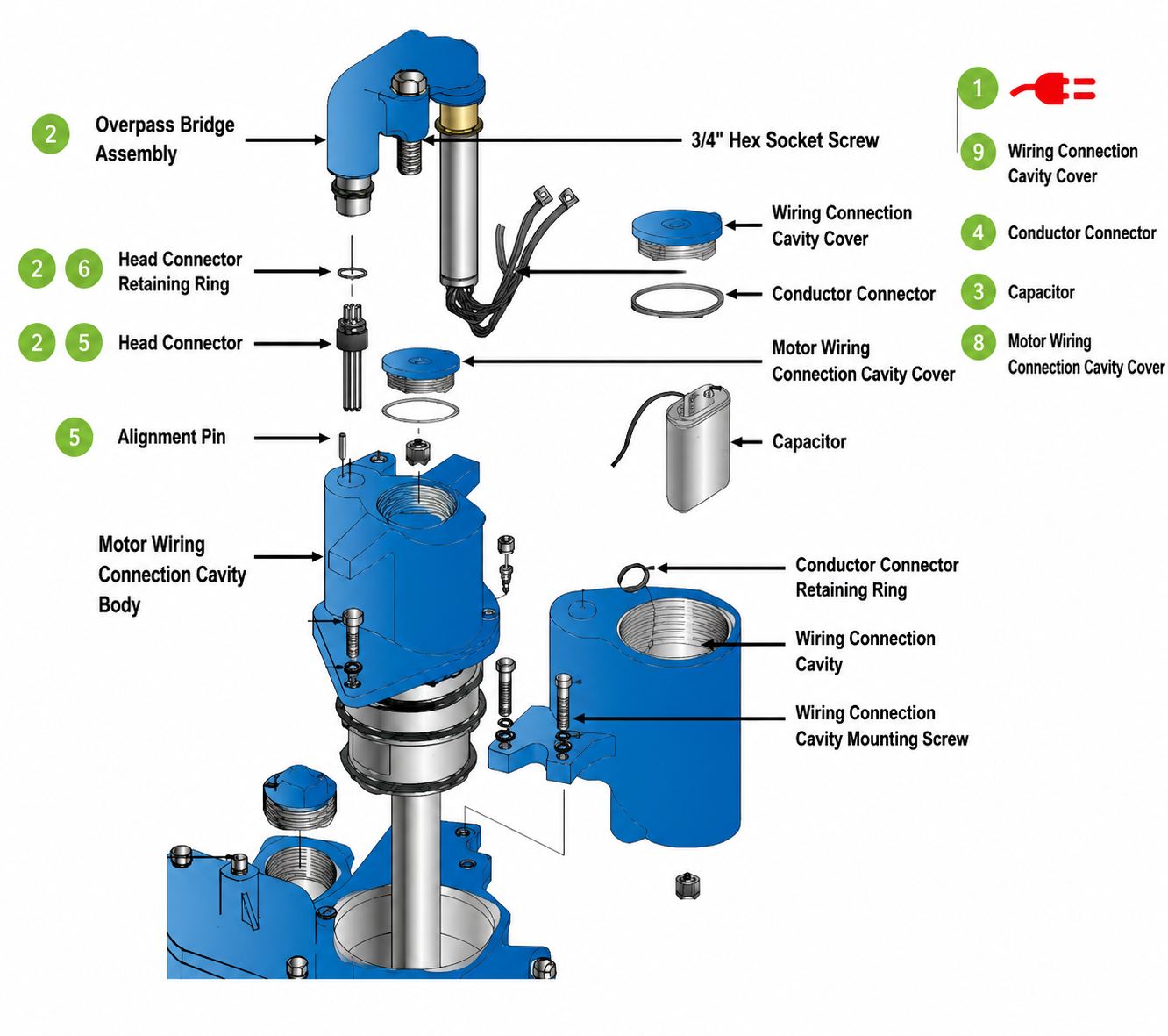
Step 4: Remove Connector Retaining Clip
Remove the retaining clip inside the connection chamber.
Carefully take out:
- Wire connector
- Overline bridge assembly
Step 5: Disconnect Motor Side Connector
Remove the motor connection chamber cover.
Disconnect the male connector wires connected to the motor wire assembly.
Remove:
- Three wire nuts
- Male connector retaining clip
Then remove the overline bridge component completely.
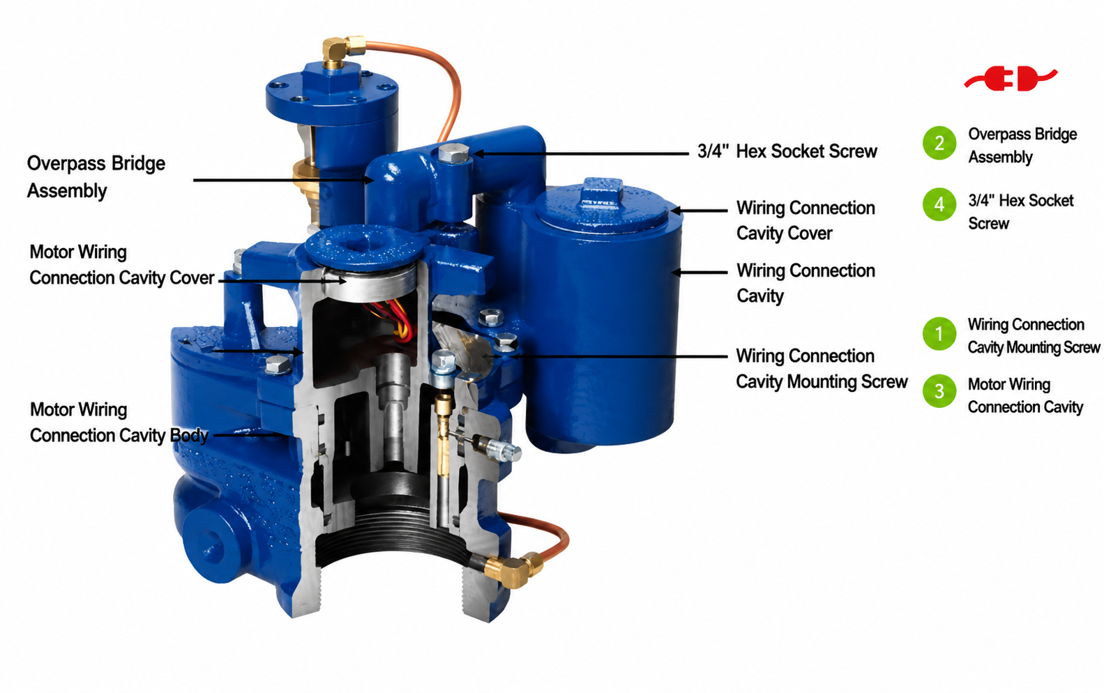
Installing the New Overline Bridge Assembly
Before installation:
Confirm:
- Correct replacement part
- Connector condition
- Wiring position
- Sealing components
Follow these installation steps:
Step 1: Disconnect Power Completely
At the power cabinet:
- Turn off the submersi submersible oil pump ble pump power
- Mark the power switch to prevent accidental operation
Step 2: Install Male Connector
Remove the male connector retaining clip from the new overline bridge assembly.
Insert the male connector into the connection chamber opening.
Reinstall:
Male connector retaining clip
Ensure the connector is firmly fixed.
Step 3: Connect Electrical Wires
For single-phase equipment:
Connect the wire connector leads to the capacitor.
For three-phase equipment:
Connect wires according to color:
- Red → Red
- Orange → Orange
- Black → Black
Always follow the correct wiring diagram.
Incorrect wiring may cause:
- Motor failure
- Wrong rotation direction
- Electrical damage
Step 4: Install Connection Chamber Cover
After completing the wiring:
Install the connection chamber cover securely.
Check:
- Sealing condition
- Screw tightening
- Proper installation position
Step 5: Install Motor Side Connector
Insert the male connector wire into the motor connection chamber.
Align it with:
the positioning pin
Make sure the connector is correctly positioned.
Step 6: Secure Connector
Install the male connector retaining clip.
Use wire nuts to connect:
Connector wires
to
Motor wires
Maintain correct color matching:
- Red → Red
- Orange → Orange
- Black → Black
Step 7: Install Motor Connection Chamber Cover
Install and tighten the motor connection chamber cover.
Confirm:
- No loose parts
- Proper sealing
- Complete protection
Step 8: Apply Lubricant to Fixing Bolt
Apply a small amount of lubricant to the thread of the:
Hexagon fixing bolt
Important:
Do not allow lubricant to contact:
- Male connector
- Female connector
Lubricant contamination may cause:
- Poor electrical conductivity
- Connection failure
Then carefully insert the shorter end of the overline bridge assembly into the connection chamber opening.
Tighten the fixing bolt securely.
- Common Submersible Fuel Pump Problems and Solutions
Although submersible oil pump rsible pumps are designed for long-term operation, incorrect installation, electrical problems or insufficient maintenance may cause failures.
The following are common problems found in fuel station operation.
Problem 1: submersible oil pump Does Not Start
Possible Causes:
- Power supply failure
Check:
- Main power supply
- Circuit breaker
- Control cabinet output
- Incorrect wiring
Check:
- Live wire connection
- Neutral wire connection
- Ground connection
- Capacitor wiring
- Motor protection activated
Check:
- Thermal overload protector
- Motor current condition
- Motor insulation problem
Check:
- Insulation resistance
Required value:
Above 20 MΩ
Solution:
- Confirm power supply
- Check wiring according to diagram
- Reset overload protection
- Test motor insulation condition
Problem 2: Pump Runs but Fuel Flow Is Low
Possible Causes:
- Incorrect pump rotation direction
- Pipeline blockage
- Low tank fuel level
- Damaged pump components
- Air entering the system
Solution:
Check:
✓ Pump rotation direction
✓ Pipeline condition
✓ Fuel level
✓ Pump operation pressure
✓ Connection sealing
Problem 3: Motor Runs in Reverse Direction
Possible Causes:
Incorrect capacitor wiring or electrical connection.
Solution:
Check:
- Capacitor wiring
- Wire connection sequence
- Electrical diagram
Correct the wiring before restarting the pump.
Problem 4: Thermal Overload Protection Trips Frequently
Possible Causes:
- Incorrect overload setting
- Motor overcurrent
- Voltage instability
- Mechanical resistance
- Pump running without fuel
Solution:
Check:
- Thermal protection setting
Recommended:
Approximately 10A
Also check:
- Power voltage
- Motor condition
- Pump installation condition
Problem 5: Poor Electrical Contact or Pump Stops Randomly
Possible Causes:
- Damaged overline bridge assembly
- Loose connector
- Bent connector pins
- Poor insulation
Solution:
Inspect:
- Overline bridge connector
- Electrical contacts
- Connector alignment
- Wiring condition
Replace damaged components if necessary.
Need Help With a Submersible Fuel Pump Problem?
If your pump has starting problems, low fuel flow, electrical faults, overload trips, or unstable operation, our team can help identify the possible cause and recommend suitable fuel station equipment and replacement components.
- Daily Maintenance Recommendations for submersible oil pumps
Regular maintenance can significantly improve:
- Equipment reliability
- Pump service life
- Fuel system stability
- Station operation efficiency
Pump Operation Inspection
Regularly check:
✓ Pump startup condition
✓ Running noise
✓ Vibration level
✓ Fuel delivery stability
Abnormal conditions include:
- Difficult startup
- Increased noise
- Reduced fuel flow
- Frequent shutdown
These conditions require immediate inspection.
Electrical System Inspection
Check regularly:
✓ Cable connections
✓ Grounding condition
✓ Control cabinet operation
✓ Thermal overload protection
Make sure:
- Wiring is secure
- No moisture enters electrical parts
- Explosion-proof sealing remains effective
Pipeline and Connection Inspection
Check:
✓ Fuel pipeline leakage
✓ Flange connections
✓ Hose condition
✓ Sealing performance
A leaking pipeline may cause:
- Reduced fuel delivery
- Safety risks
- Fuel loss
Long-Term Storage Maintenance
If the submersible oil pump remains unused for a long period:
Before restarting:
- Check motor rotation
- Check insulation resistance
- Check electrical connections
- Confirm pump condition
Final Inspection Checklist Before Operation
Before the fuel station officially starts operation, complete the following inspection.
Mechanical Inspection
Confirm:
✓ Pump installed vertically
✓ Riser pipe securely connected
✓ Outlet pipeline correctly installed
✓ No leakage
Electrical Inspection
Confirm:
✓ Power wiring correct
✓ Grounding reliable
✓ Cable sealing completed
✓ Explosion-proof requirements satisfied
Motor Inspection
Confirm:
✓ Insulation resistance above 20 MΩ
✓ Correct rotation direction
✓ Stable operation
System Operation Test
Confirm:
✓ Pump starts normally
✓ Fuel delivery is stable
✓ No abnormal noise
✓ Control signal works correctly
Conclusion
The submersible fuel pump is one of the most important components in a modern fuel station system. Reliable operation depends not only on the pump itself, but also on correct mechanical installation, accurate electrical wiring, proper commissioning and regular maintenance.
By following professional installation standards, maintaining correct electrical connections and performing routine inspections, fuel station operators can improve system stability, reduce unexpected downtime and extend equipment service life.
A properly installed and maintained submersible oil pump provides safer, more efficient and more reliable fuel delivery for modern gas station operations.