
Gas Station Vapor Recovery System: Design, Components and Key Requirements
News 2026年 8月 17日 36
Gasoline vapor is generated during fuel unloading, storage and vehicle refueling. A properly designed vapor recovery system captures these vapors, controls tank pressure and reduces uncontrolled VOC emissions.VOCs from gasoline distribution are important precursors to ground-level ozone and secondary PM₂.₅ pollution.
According to GB 20952—2020, the current national emission standard for gasoline filling stations in China, vapor emission control is mandatory across the whole process: fuel unloading, underground storage and vehicle refueling. Industry monitoring data shows stations without effective vapor recovery lose roughly 2–2.5 kg gasoline per tonne of fuel sold. A complete Stage I + Stage II system can cut fugitive vapor emissions by 85%–90%. When equipped with Stage Ⅲ treatment units, overall VOC removal efficiency can exceed 95%.
1. What Is a Gas Station Vapor Recovery System?
A gas station vapor recovery system is designed to capture gasoline vapor displaced during tanker unloading and customer refueling.
The mainstream system is divided into three tiers: Stage I, Stage II and optional Stage Ⅲ vapor recovery.
A typical full set of equipment includes:
- Stage I vapor recovery system
- Stage II vapor recovery system (balance type or vacuum-assisted type)
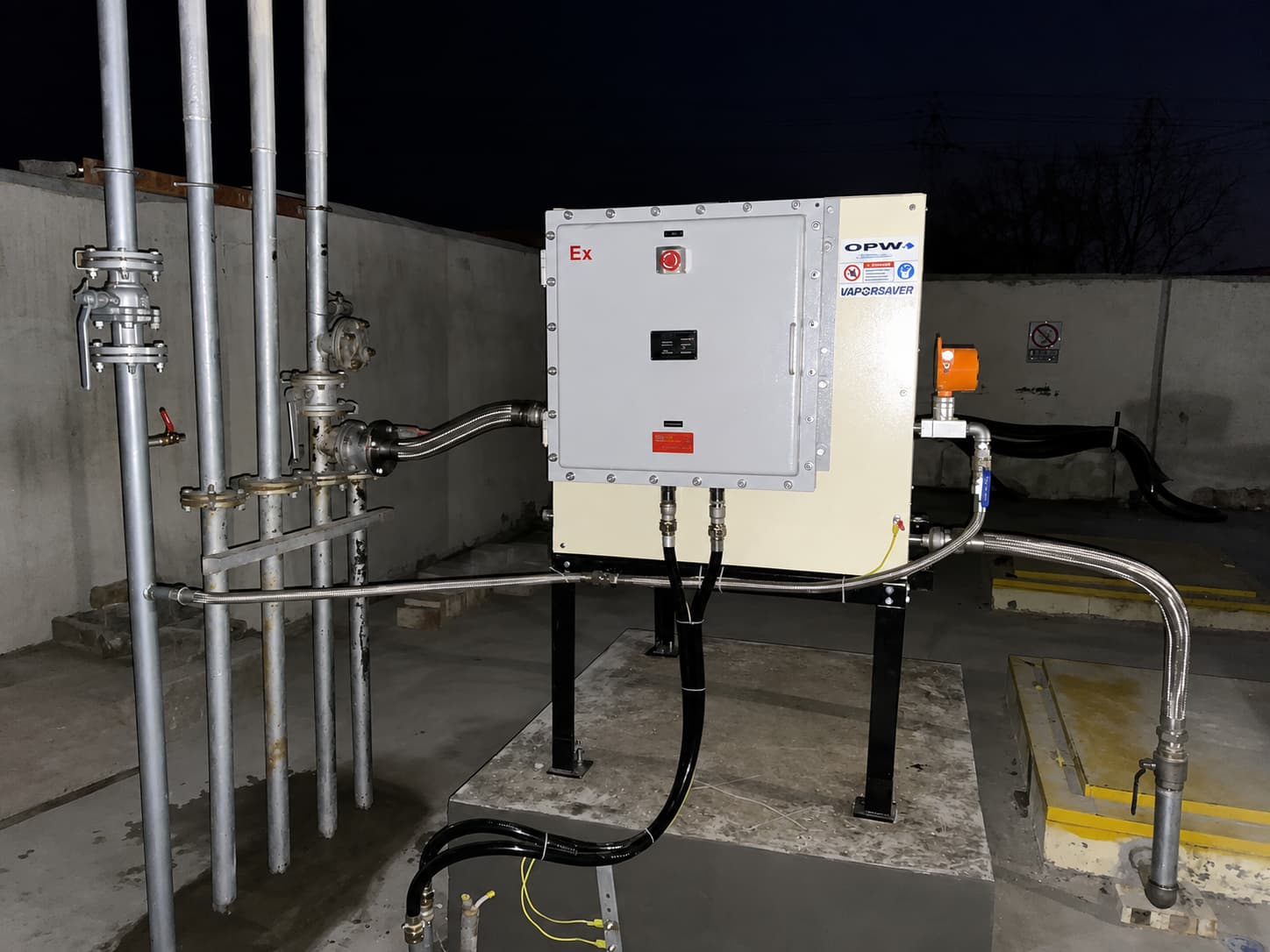
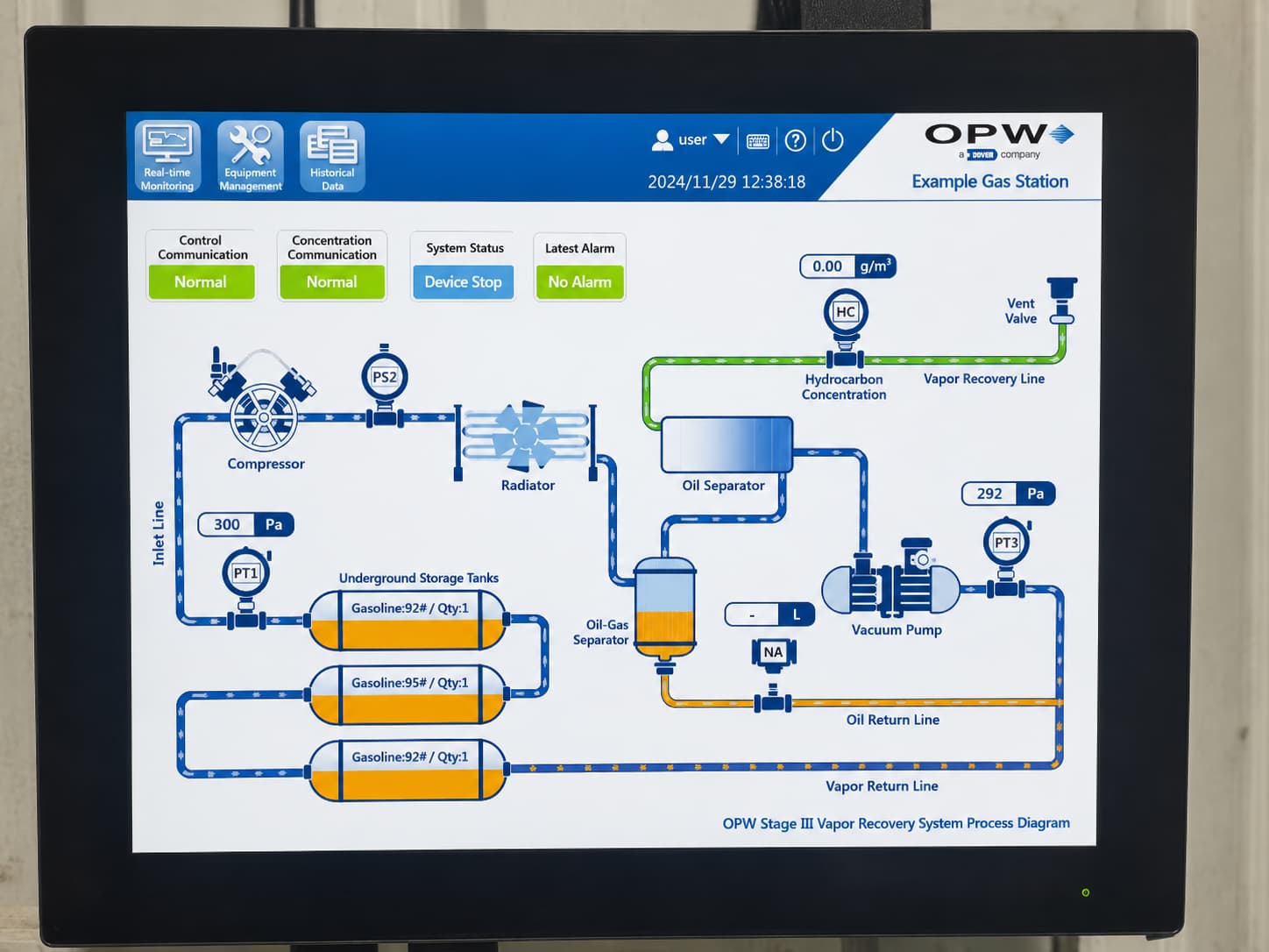
- Optional Stage Ⅲ vapor treatment unit
- Vapor recovery piping and manifolds
- Dry-break vapor recovery connectors
- Tank vent assembly and pressure/vacuum (P/V) valves
- Vapor-liquid separators / condensate traps
- Pipeline leak detection and continuous monitoring equipment
The basic working principle:
Gasoline fills the tank → vapor space shrinks and vapor is displaced → vapor is captured through closed pipelines → vapor is returned or treated.
The system suppresses uncontrolled vapor venting while maintaining safe operating pressure inside underground storage tanks.
Note: An increasing number of modern passenger vehicles adopt ORVR (Onboard Refueling Vapor Recovery). Mismatch between Stage II hardware and ORVR vehicles often leads to abnormal gas-liquid ratio and extra air ingress, which must be considered in design and commissioning.
2. Stage I vs. Stage II Vapor Recovery
The two core systems operate in different working phases of gas stations.
Stage I Vapor Recovery — Fuel Unloading
Stage I works during gasoline delivery from tanker trucks to underground storage tanks.
As liquid gasoline enters the tank, the available vapor space reduces and gasoline vapor is squeezed out.
Instead of venting vapors directly to air:
Underground Tank → Vapor Recovery Pipe → Tanker Truck
Displaced vapors are transferred back into the delivery tanker.
GB 20952—2020 mandates submerged unloading: the outlet of the liquid unloading pipeline shall be less than 200 mm above the tank bottom to minimize splash and extra vapor generation.
International reference: US EPA requires Stage I recovery efficiency ≥90%.
Stage II Vapor Recovery — Vehicle Refueling
Stage II operates while refueling motor vehicles.
When gasoline flows into a vehicle fuel tank, existing gasoline vapor inside the vehicle tank is displaced.
The Stage II system captures vapor through dedicated vapor recovery nozzles and transports vapors back to underground storage tanks.
Typical flow path:
Vehicle Tank → Vapor Recovery Nozzle → Vapor Recovery Pipe → Underground Tank
Vapor is temporarily stored in the underground tank rather than released.
EU regulation requires mandatory Stage II installation for service stations with annual gasoline throughput over 3000 m³, with minimum vapor capture efficiency ≥85%.
3. Key Components of a Vapor Recovery System
Vapor Recovery Piping
Vapor pipelines connect underground storage tanks with Stage I and Stage II facilities.
Design parameters to be strictly controlled:
- Nominal pipe diameter (minimum DN50)
- Pipeline slope and routing
- Connection layout
- Condensate drainage design
Liquid condensate accumulating inside vapor lines raises flow resistance and degrades overall recovery performance. GB 20952—2020 explicitly requires management of condensate in vapor pipelines and closed recovery of collected liquid.
Engineering standard: vapor pipelines shall slope towards underground tanks with a minimum gradient of 1% so condensed gasoline flows back into tanks naturally. Condensate traps shall be installed for long-distance pipelines.
Vapor Recovery Connector
The dry-break vapor recovery connector provides sealed linkage between tankers and station vapor pipelines during unloading.
Key performance requirements:
- Reliable airtight sealing
- Unique fuel identification to prevent misconnection
- Secure quick coupling
- Interoperability with tanker vapor recovery equipment
Even perfectly installed underground piping will suffer massive vapor leakage if connectors are damaged or poorly matched.
Pressure/Vacuum (P/V) Valve
Core pressure protection component. Common factory setting range:
Positive opening pressure: +150 Pa ~ +300 Pa
Negative opening pressure: -150 Pa ~ -300 Pa
It prevents dangerous overpressure or excessive vacuum inside tanks and limits direct atmospheric venting.
Vacuum Pump Assembly
Only equipped for vacuum-assisted Stage II systems, providing stable suction for vapor recovery nozzles. Balance-type Stage II systems do not require vacuum pumps.
4. Gas-Liquid Ratio: 1.0–1.2
The gas-liquid ratio is the most critical performance indicator for Stage II vapor recovery.
Per GB 20952—2020:
Qualified gas-liquid ratio range: 1.0–1.2
Test condition: stable dispensing flow rate of 20 L/min.
In simple definition: under standard test conditions, the volume of recovered vapor shall reach 100%–120% of the volume of dispensed gasoline.
Example: When the dispenser outputs 100 L gasoline, the recovered vapor volume should be between 100 L and 120 L.
- Ratio below 1.0: insufficient vapor capture, vapor escape risk
- Ratio above 1.2: excessive air suction, often caused by ORVR mismatch, nozzle misadjustment or joint leakage
Domestic environmental inspection statistics show abnormal gas-liquid ratio accounts for more than 50% of all vapor recovery non-compliance records.
If one single measurement exceeds the limit by ≤0.1, repeated testing shall be carried out, and compliance shall be judged by the average result.
5. Vapor Recovery Pipe Liquid Resistance
Vapor pipelines must guarantee low flow resistance for vapor transportation.
GB 20952—2020 defines upper pressure limits for liquid resistance testing with nitrogen supply:
表格
| Nitrogen FlowMaximum Allowable Pressure | |
|---|---|
| 18 L/min | 40 Pa |
| 28 L/min | 90 Pa |
| 38 L/min | 155 Pa |
Liquid resistance testing shall be performed at least once per year in accordance with HJ 1249-2022.
Common causes of excessive pipeline resistance:
- Improper pipeline routing
- Overlong pipe runs
- Accumulated liquid condensate
- Internal pipe blockages
- Incorrect pipe diameter selection
- Damaged valves and fittings
Therefore, vapor pipeline design cannot merely realize physical connection between equipment points; flow resistance must be calculated and controlled.
6. System Tightness Is Critical
A vapor recovery system cannot operate effectively without good airtightness.
High-risk leakage locations include:
- Tank manhole connections
- Vapor recovery quick connectors
- All valves
- Pipe flanges and threaded joints
- Dispenser manholes
- Recovery nozzles
- Monitoring instrument interfaces
GB 20952—2020 specifies minimum residual pressure requirements for tightness testing. The threshold value depends on underground tank vapor space volume and the quantity of connected refueling nozzles.
Testing procedure: pressurize the whole system to 500 Pa, hold pressure for 5 minutes and record residual pressure.
The cited example for tank vapor space of 3,785 L:
- 1–6 connected nozzles: minimum residual pressure 301 Pa
- 7–12 connected nozzles: minimum residual pressure 294 Pa
- 13–18 connected nozzles: minimum residual pressure 284 Pa
- 19–24 connected nozzles: minimum residual pressure 274 Pa
- Over 24 connected nozzles: minimum residual pressure 267 Pa
For formal acceptance, full parameter tables in GB 20952—2020 shall be followed according to actual project conditions.
Additional leakage control indicators: local vapor concentration at any sealed joint ≤ 500 μmol/mol; site boundary non-methane hydrocarbon hourly average concentration ≤ 4.0 mg/m³.
7. Common Vapor Recovery Problems
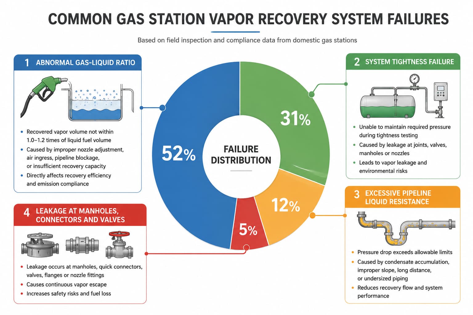
Field investigation data from domestic gas station compliance inspections shows the distribution of typical failures:
- Abnormal gas-liquid ratio (~52%)
- System tightness failure (~31%)
- Excessive pipeline liquid resistance (~12%)
- Permanent leakage at manholes, connectors and P/V valves (~5%)
Low Gas-Liquid Ratio
Potential causes:
- Malfunctioning vapor recovery nozzle
- Blocked vapor recovery pipeline
- System leakage
- Insufficient pumping capacity (vacuum-assisted type)
- Improper system parameter calibration
Recommended actions: inspect nozzle seals, clear pipeline condensate, check all joints for leakage, re-calibrate vacuum pump flow.
High Gas-Liquid Ratio
Potential causes:
- Excessive air drawn into the closed system
- Incorrect nozzle adjustment
- Stuck or faulty valves
- Over-high recovery suction flow
- Incompatibility with ORVR vehicles
Recommended actions: check for external air ingress, adjust nozzle air shutter, match nozzle specifications for ORVR traffic.
High Pipeline Resistance
Potential causes:
- Condensate accumulation inside pipelines
- Partial pipe blockage
- Unqualified pipeline slope
- Overlong piping layout
- Improper pipe diameter
Recommended actions: drain condensate traps, verify pipeline gradient, remove obstructions, optimize pipeline layout.
System Fails Tightness Test
Inspection sequence:
Underground Tank → Manholes → Valves → Vapor Recovery Piping → All Connections → Dispenser Nozzles
Locate leakage points before replacing expensive core components.
8. What Should Be Considered During System Design?
Vapor recovery design must evaluate the complete underground fuel handling system instead of treating individual components separately.
Core design considerations:
- Quantity and capacity of underground storage tanks
- Number of fuel dispensers and gasoline nozzles
- Vapor pipeline diameter, total length and routing
- Pipeline gradient and condensate drainage layout
- Selection: balance-type or vacuum-assisted Stage II
- Stage I and Stage II layout coordination
- Tank pressure protection strategy (P/V valve setting)
- Leak monitoring and continuous vapor monitoring configuration
- Local environmental protection standards
- ORVR vehicle penetration rate in the service area
- Reserved space for future Stage Ⅲ vapor treatment expansion
- Explosion-proof classification for all electrical equipment
Conclusion
A qualified vapor recovery system is far more than a simple set of pipes connecting underground tanks and dispensers.
Overall performance relies on integrated control of pipeline layout, sealing connections, valve settings, nozzle performance, tank pressure balance, gas-liquid ratio, pipeline liquid resistance and whole-system tightness.
For projects adopting GB 20952—2020 as the governing standard, the core control parameters are summarized below:
- Gas-liquid ratio of Stage II system: 1.0–1.2 (test flow: 20 L/min)
- Pipeline liquid resistance limits: ≤40 Pa / 90 Pa / 155 Pa under corresponding nitrogen flow
- System tightness test: minimum residual pressure determined by tank vapor space and connected nozzle quantity
- Joint leakage limit: vapor concentration ≤ 500 μmol/mol
Whether for new-built gas stations or retrofitting existing facilities, these indicators need coordinated consideration in schematic design, construction acceptance and routine system commissioning. The system delivers triple value: environmental compliance, reduction of gasoline economic loss, and mitigation of flammable vapor safety risks.
Planning a new gas station or upgrading an existing vapor recovery system?
We can help evaluate the tank configuration, vapor recovery piping, connections and related underground equipment based on your project requirements.