
Gas Station Lightning Protection and Anti-Static Safety: Grounding, Bonding and Key Requirements
News 2026年 9月 13日 59
Introduction
Gas station lightning protection is not simply about installing a grounding wire or connecting equipment to an earth electrode.
A complete protection system should also consider anti-static protection, equipment grounding, pipeline bonding, tanker grounding, surge protection and human-body static elimination.
Many small-scale construction and overseas renovation projects install only basic grounding devices. However, they may overlook pipeline bonding, tanker grounding, static-release facilities, surge protection and the different grounding resistance requirements for different applications.
This guide integrates practical engineering requirements for gas station lightning protection, anti-static protection, equipment grounding, pipeline bonding, tanker unloading safety, human-body static elimination, surge protection, grounding parameters, inspection and acceptance.
It can be used as a technical reference for gas station construction, renovation, equipment procurement, bidding, commissioning and site acceptance.
1. Core Concept: Lightning Protection ≠ Static Protection
Lightning protection and static electricity protection are related, but they address different risks.
1.1 Lightning Protection
Lightning protection is designed to control external lightning hazards, including:
- Direct lightning strikes
- Induced lightning
- Lightning wave intrusion
- Lightning-related transient overvoltage
The protection system should consider fuel storage tanks, canopies, buildings, pipelines, electrical systems and information systems, together with the station’s [hazardous area classification].
1.2 Anti-Static Protection
Anti-static protection controls static electricity generated inside the station through:
- Fuel flow and fluid friction
- Pipeline transportation
- Fuel loading and unloading
- Vehicle movement
- Hose and equipment operation
- Human-body friction and movement
Both systems should be designed, installed and inspected as part of the overall electrical safety system.
A gas station should not rely on a single grounding point to control every lightning and static-electricity risk.
2.Gas Station Lightning Protection Grounding Requirements
2.1 Storage Tank Grounding Requirements
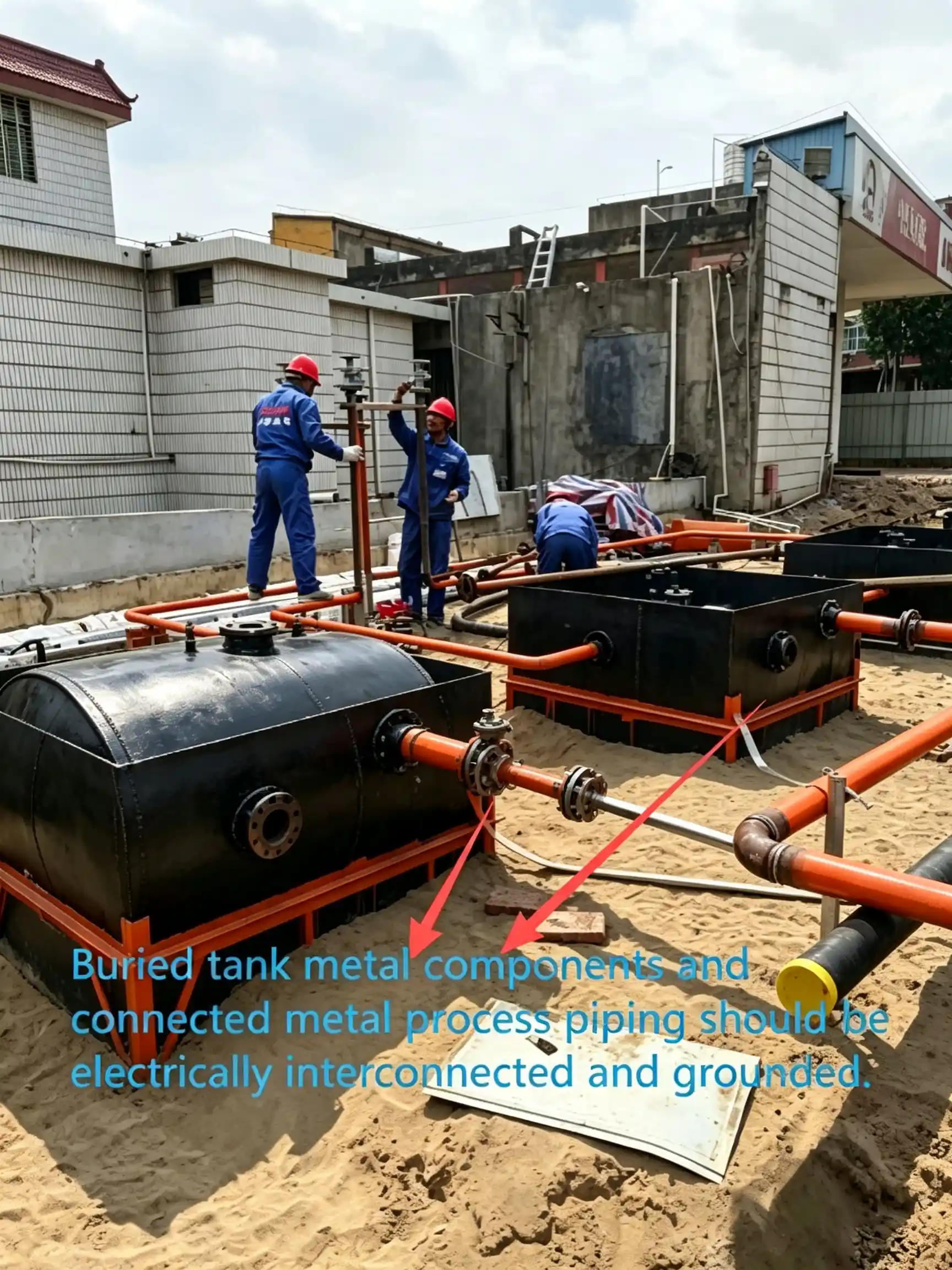
Steel oil tanks, LPG storage tanks, LNG storage tanks, CNG cylinder banks, hydrogen storage vessels and liquid-hydrogen tanks require reliable lightning-protection grounding.
The key requirements include:
- Provide a minimum of 2 grounding points for each applicable metal storage tank.
- Grounding points should provide reliable electrical continuity and equipotential bonding.
- Buried tank metal components and connected metal process piping should be electrically interconnected and grounded.
- CNG and hydrogen tube-trailer parking or unloading areas should have 2 temporary fixed lightning-protection grounding devices.
The purpose of multiple grounding points is to provide a reliable path for fault and lightning currents and reduce the possibility of an isolated metal section remaining at a dangerous potential.
2.2 Common Site-Wide Grounding System
A gas station normally contains several grounding functions, including:
- Lightning-protection grounding
- Anti-static grounding
- Protective grounding
- Working grounding
- Information-system grounding
These grounding systems should preferably share a common grounding arrangement where the design permits.
Maximum common grounding resistance: ≤4Ω
This is one of the most important parameters when checking a gas station grounding system.
The grounding design should therefore be considered as a complete network rather than as individual grounding points installed independently at each piece of equipment.
2.3 Special Grounding Rule for LPG Tanks with Cathodic Protection
Under specific cathodic-protection arrangements, an LPG storage tank may not require a separate lightning and static grounding system.
Two methods should be distinguished.
Sacrificial-Anode Method
When sacrificial-anode cathodic protection is used:
- Grounding resistance: ≤10Ω
- Copper-core connecting conductor cross-section: ≥16 mm²
Impressed-Current Method
When impressed-current cathodic protection is used:
- Use zinc rods or magnesium-zinc composite electrodes.
- Grounding resistance: ≤10Ω
- Copper-core connecting conductor cross-section: ≥16 mm²
The cathodic-protection arrangement must be properly designed and maintained before relying on this special grounding condition.
3. Pipeline Lightning and Static Protection
Above-ground or trench-installed fuel and gas pipelines can become an important path for static accumulation and induced lightning currents.
For oil-product, LPG, LNG, CNG and hydrogen pipelines:
- Provide a combined grounding system for anti-static protection and induced-lightning protection.
- Maintain electrical continuity between connected metallic sections.
- Pipeline grounding resistance should be ≤30Ω.
Pipeline Bonding
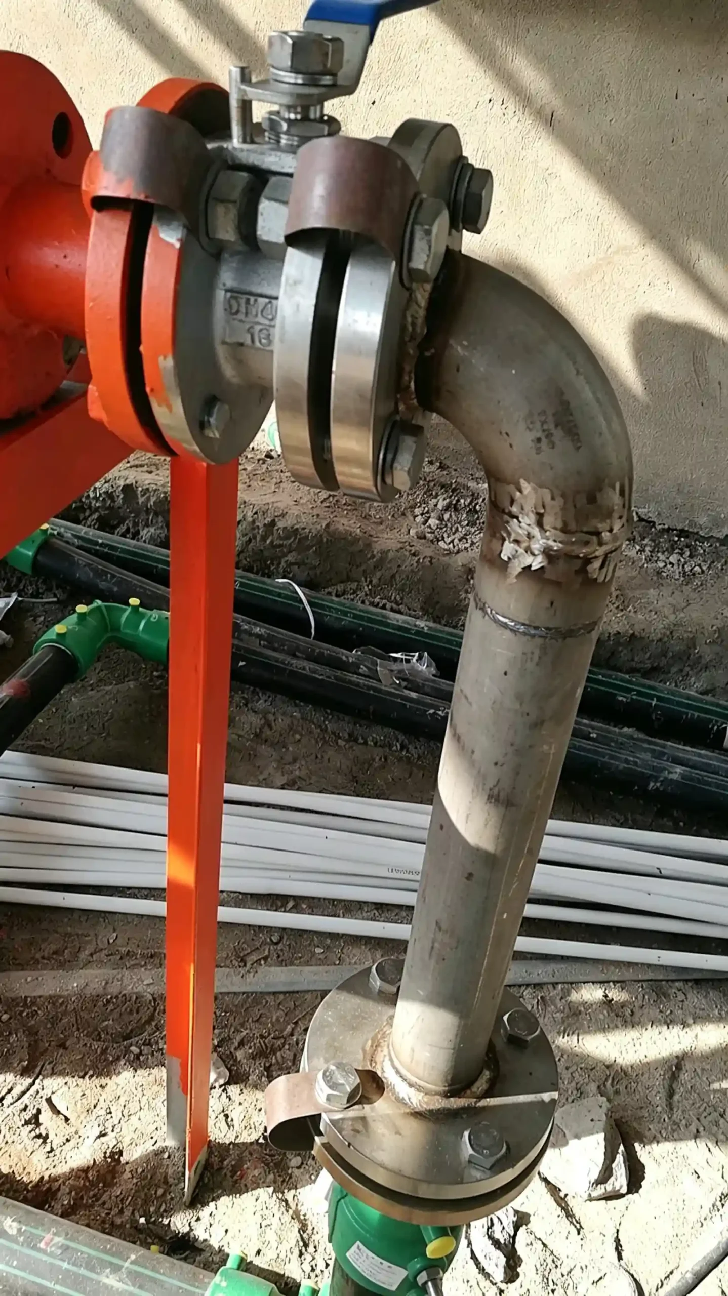
Metal flanges and hose connections in hazardous process areas should maintain reliable electrical continuity through bonding.
Metal bonding jumpers should be provided across:
- Pipeline flanges
- Hose connections
- Metallic joints
- Other connections where electrical continuity cannot otherwise be guaranteed
For flanges with 5 or more connecting bolts, bonding may be omitted under non-corrosive conditions where reliable electrical continuity is maintained.
For older pipelines, few-bolt flanges, corrosive environments or questionable electrical continuity, bonding should be treated as a critical inspection item.
4. Oil and Gas Vent Pipe Grounding
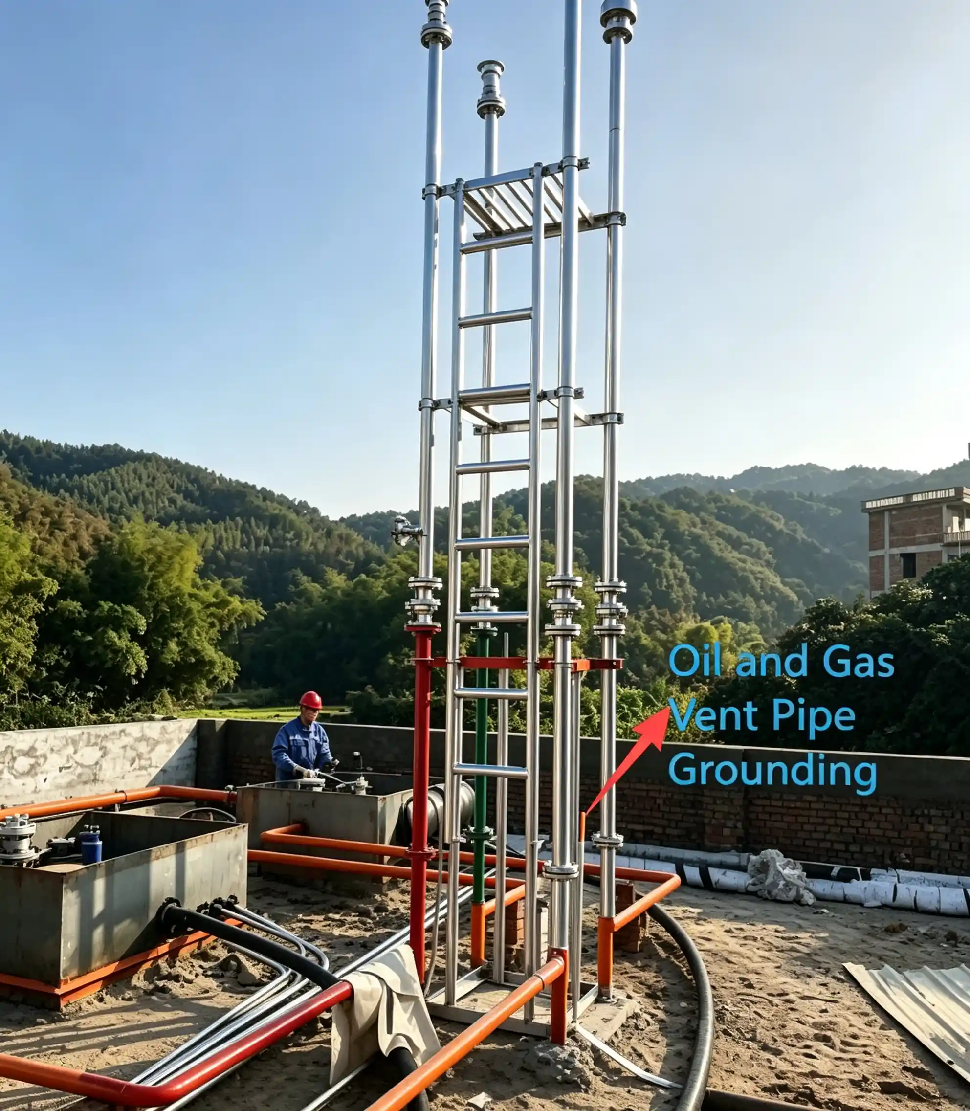
Vent pipes are exposed to fuel vapors and therefore require careful grounding consideration.
When the oil-gas vent pipe is connected to the station-wide common grounding system, it does not need a separate lightning-protection grounding connection.
The important point is to verify that the vent pipe has reliable electrical continuity with the grounding network.
5. Lightning Protection for Canopies and Station Buildings
Canopies and station buildings may require protection against direct lightning strikes depending on their lightning-risk assessment and design conditions.
Lightning protection may use:
- Lightning protection tapes
- Lightning protection meshes
- Other compliant air-termination arrangements
Metal Canopy Roof as a Natural Lightning Receptor
A metal canopy roof may be used as a natural lightning receptor when the required conditions are satisfied.
5.1 Continuous Electrical Connection
Metal roof panels must maintain durable electrical continuity.
Acceptable connection methods can include:
- Welding
- Crimping
- Seaming
- Screwed connections
- Bolted connections
- Other reliable permanent electrical connections
5.2 Minimum Metal Sheet Thickness
The following minimum thicknesses apply to the specified metal roofing materials:
| Material | Minimum Thickness |
|---|---|
| Hot-dip galvanized steel | ≥0.5 mm |
| Aluminum | ≥0.65 mm |
| Zinc | ≥0.7 mm |
5.3 No Full Insulating Covering
The metal sheet should not have an insulating coating or covering that prevents the roof from functioning as a continuous electrical path.
The roof should also be checked to ensure that combustible materials are not located directly underneath the metal sheet where prohibited by the design requirements.
6. Tank-Truck Unloading Area: Static Electricity Control
Fuel unloading is one of the most important static-electricity control points at a gas station.
During unloading, fuel movement and equipment connections can create electrostatic charges. If the tanker and station equipment are at different electrical potentials, a spark can become an ignition source.
6.1 Temporary Static-Grounding Device
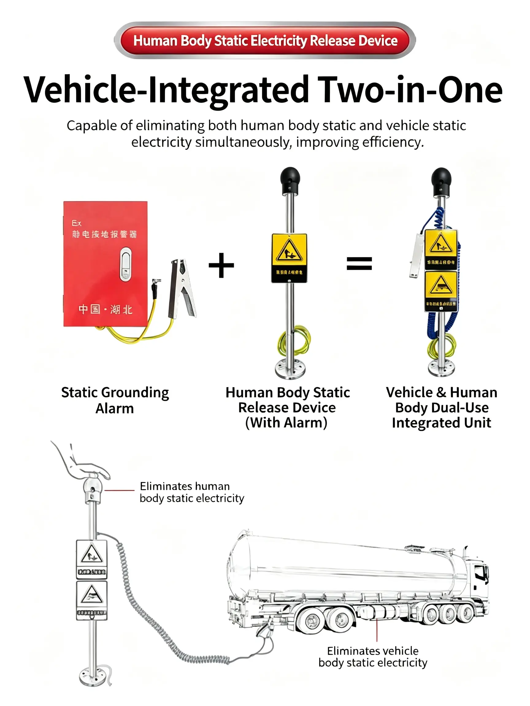
The unloading area for oil, LPG, LNG and liquid-hydrogen tank trucks should be equipped with a temporary anti-static grounding device.
The system should provide a reliable electrical connection between the tanker and the station grounding system.
6.2 Static-Grounding Monitor
A static-grounding monitor should be installed to detect:
- Grounding connection status
- Bonding continuity
- Grounding circuit interruption
For automated unloading systems, the grounding monitor can be integrated with the unloading control system so that unloading is prevented or interrupted when the required grounding condition is not satisfied.
6.3 Location of Fixed Grounding Devices
Fixed grounding devices used for tanker anti-static bonding should not be installed inside Explosive Hazardous Zone 1.
The location should allow operators to establish a reliable grounding connection before the unloading operation begins.
7. Tanker, Hose and Vapor-Recovery Bonding
Grounding is not limited to the tanker itself.
Electrical continuity must also be maintained through unloading equipment.
Oil unloading hoses
The oil-unloading hose and its end fittings should maintain reliable electrical continuity.
Vapor-recovery hoses
Vapor-recovery hoses and their end fittings should also maintain reliable electrical continuity.
Grounding clamp connection
The grounding clamp should make reliable electrical contact with an appropriate conductive metal surface.
Paint, heavy rust, dirt or other insulating contamination can increase contact resistance and create a false grounding condition.
Therefore, grounding connections should be inspected before unloading.
8. Human-Body Static Protection
Human-body static electricity is often overlooked during gas station construction and operation.
Under dry conditions, a human body can accumulate static voltage in the range of 5,000–15,000 V.
Although the voltage is high, the total stored energy is normally limited. However, a static discharge can still become an ignition source where flammable vapor is present.
8.1 Human-Body Static-Release Facilities
Static-release facilities can be installed at:
- Tank farm entrances
- Fuel unloading areas
- Maintenance areas
- Other controlled work zones
The static-release device should be reliably connected to the anti-static grounding system.
The grounding resistance of the applicable anti-static grounding device should be controlled according to the project design requirements, with ≤100Ω as the relevant anti-static grounding resistance limit.
8.2 Personnel Operating Rules
Personnel entering hazardous working areas should:
- Discharge accumulated static electricity before entering or beginning work.
- Wear appropriate anti-static work clothing.
- Wear anti-static safety footwear.
- Avoid activities that can rapidly generate static electricity.
Inside hazardous areas, avoid unnecessary actions such as:
- Putting on or removing clothing
- Beating or shaking clothing
- Combing hair
- Other activities that can generate significant static charges
9. Static Electricity During Self-Service Refueling
Static electricity can also occur during normal customer refueling.
The risk can increase under cold and dry environmental conditions.
Gas stations can reduce this risk through clear operating reminders.
Customers should be encouraged to:
- Touch an appropriate static-discharge point before refueling when provided.
- Avoid unnecessary movement in and out of the vehicle during refueling.
- Follow the station’s safety instructions.
Re-entering a vehicle during refueling can allow static charge to accumulate again on the human body.
10. Surge and Lightning Protection for Power and Information Systems
Lightning protection does not end at the grounding grid.
Lightning-induced surges can enter a gas station through:
- Power cables
- Control cables
- Communication cables
- Signal circuits
- Monitoring systems
For this reason, surge protection should be considered together with grounding and lightning protection.
10.1 Power Supply System
A TN-S system is preferred for the 380/220 V power distribution system.
Where the external incoming power supply is 380 V, a TN-C-S system may be used where permitted by the design.
The following should be grounded:
- Metallic cable sheaths
- Protective steel conduits
- Relevant metallic cable protection systems
Cable metallic sheaths and protective steel conduits should be grounded at both ends where required by the system design.
A suitable Surge Protective Device (SPD) should be installed at the power supply end according to the equipment withstand-voltage requirements.
Need help reviewing your station’s electrical and grounding configuration? Contact our technical team to discuss your project.
11. Protection of Dispensers, Monitoring and Information Systems
Fuel dispensers, monitoring systems and communication equipment contain sensitive electronic components.
Lightning-induced surges can damage:
- Dispenser control boards
- PLCs
- Monitoring equipment
- Communication equipment
- Data transmission equipment
- Other electronic control devices
Information-system wiring should use:
- Armored cables, or
- Conductors installed in steel conduits
The metallic armor and steel conduits should be grounded at both ends.
Surge protection devices should be installed at the appropriate ends of power and signal circuits according to the equipment’s voltage withstand capability.
A complete lightning protection strategy therefore requires more than grounding the equipment enclosure. Power circuits and signal circuits must also be considered.
12. Static-Conductive and Non-Conductive Plastic Piping
Plastic piping requires special attention because electrical continuity cannot be assumed in the same way as with continuous metallic piping.
Conductive thermoplastic piping
Where a conductive liner is used, the conductive liner should be reliably grounded.
Non-conductive thermoplastic piping
For non-conductive thermoplastic piping:
- Exposed non-buried thermoplastic components should maintain reliable grounding where required.
- Electro-fusion connection points should be properly protected or sealed where applicable.
- Other conductive components of pipes and fittings should be grounded.
The objective is to prevent isolated conductive sections from becoming uncontrolled sources of electrostatic potential.
13. Grounding-Resistance Reference Table
Different grounding applications have different resistance limits.
| Grounding Type | Maximum Resistance | Typical Application |
|---|---|---|
| Site-wide common lightning-protection grounding | ≤4Ω | Storage tanks, canopy, main protective grounding |
| LPG sacrificial-anode cathodic-protection grounding | ≤10Ω | LPG tank cathodic-protection system |
| Anti-static & anti-induced-lightning grounding for process pipelines | ≤30Ω | Oil and gas process pipelines |
| Anti-static grounding device | ≤100Ω | Static-release facilities and local anti-static grounding |
Why the values should not be confused
A common site mistake is to apply 100Ω as a universal grounding target.
This is incorrect because different grounding systems serve different purposes.
The engineering team should identify:
- What is being grounded?
- What is the grounding system intended to protect?
- What resistance limit applies to that specific system?
- Is the connection electrically continuous?
- Has the system been tested after installation?
Grounding resistance should therefore be checked according to the specific application rather than using one value for the entire station.
14. 8 Typical On-Site Construction Mistakes
Mistake 1: Completing equipment grounding but ignoring human-body static
Equipment may be grounded correctly while personnel static protection is overlooked.
Mistake 2: Using 100Ω as the grounding target for everything
Different applications have different resistance requirements. A site-wide common grounding system may require ≤4Ω, while other anti-static systems have different limits.
Mistake 3: Installing tanker grounding studs inside Zone 1
Fixed anti-static grounding devices for tanker unloading should not be installed inside Explosive Hazardous Zone 1.
Mistake 4: Missing bonding jumpers
Few-bolt flanges, aging connections and deteriorated hoses may lose electrical continuity if bonding is not properly maintained.
Mistake 5: Insulating a metal canopy roof
A thick insulating coating can interrupt electrical continuity and prevent the metal roof from functioning as a natural lightning receptor.
Mistake 6: Ignoring signal-circuit surge protection
Protecting only the main power supply does not necessarily protect sensitive electronic and communication systems.
Mistake 7: Connecting grounding clamps to painted or heavily corroded surfaces
A grounding clamp connected to an insulating surface may appear connected while providing poor electrical continuity.
Mistake 8: Failing to conduct periodic inspections
Grounding grids, bonding conductors, hose connections and SPDs can deteriorate over time due to corrosion, mechanical damage or environmental exposure.
15. Periodic Inspection and Acceptance
Lightning and anti-static protection should not be treated as a one-time commissioning activity.
A practical inspection program should include the following.
Grounding Resistance Testing
Test lightning-protection and anti-static grounding resistance at least every 6 months and maintain the test records.
Monthly Visual and Functional Checks
Check:
- Bonding jumpers
- Hose electrical continuity
- Tanker grounding points
- Static-grounding monitors
- Grounding clamps
- SPD status indicators
- Visible corrosion or mechanical damage
Pre-Thunderstorm / Rainy-Season Inspection
Before periods of frequent thunderstorms and heavy rainfall, inspect:
- Grounding grids
- Grounding conductors
- Connection points
- Corrosion conditions
- Lightning-protection components
- Surge-protection devices
Any damaged or corroded grounding connection should be repaired and retested.
16. Gas Station Lightning & Anti-Static Inspection Checklist
Before commissioning or accepting a gas station project, engineers and owners can use the following checklist:
| Inspection Item | Key Requirement |
|---|---|
| Storage tank grounding | Minimum 2 grounding points where applicable |
| Common grounding system | ≤4Ω |
| LPG cathodic-protection grounding | ≤10Ω where applicable |
| Process pipeline grounding | ≤30Ω |
| Anti-static grounding device | ≤100Ω |
| Tanker grounding | Temporary anti-static grounding provided |
| Grounding monitoring | Grounding/bonding status detectable |
| Tanker grounding location | Fixed grounding device outside Zone 1 |
| Pipeline bonding | Electrical continuity maintained |
| Hose continuity | Unloading and vapor-recovery hoses electrically continuous |
| Canopy protection | Lightning protection provided where required |
| Metal canopy roof | Electrical continuity maintained if used as receptor |
| Power SPD | Installed according to system requirements |
| Signal SPD | Provided for sensitive electronic circuits where required |
| Cable armor | Grounded appropriately |
| Steel conduits | Grounded appropriately |
| Grounding records | Test reports maintained |
| Periodic inspection | Regular testing and maintenance completed |
Conclusion
A gas station may look safe on the surface—but can you prove that its lightning and anti-static protection will work when it matters most?
A grounding wire can be installed. A grounding point can be labeled. A test report can be filed.
But safety is not about what is installed. It is about what still works when lightning strikes, static builds up, or a connection suddenly fails.
That is why every gas station should occasionally be viewed from a different perspective:
If something goes wrong today, where will the energy go—and what will stop it from becoming an ignition source?
That question may reveal more than another inspection checklist ever will.
If you are designing a new station or reviewing an existing one, contact us to discuss your equipment and technical requirements.