
Gas Station Hazardous Area Classification and Explosion-Proof Requirements
News 2026年 8月 23日 66
Gas stations handle gasoline and other flammable fuels, which means certain areas may contain flammable vapor during normal operation or under abnormal conditions.
For this reason, hazardous area classification and explosion-proof protection are important parts of gas station design.
According to GB 50156—2021 and GB 50058—2014, explosive gas atmospheres can be classified into Zone 0, Zone 1 and Zone 2 according to how frequently and how long an explosive gas mixture may be present.
This article explains the basic classification, typical hazardous areas at gasoline stations, explosion-proof electrical requirements, combustible gas detection and practical protection measures.
1. What Is a Hazardous Area at a Gas Station?
A hazardous area is a location where a flammable gas or vapor mixture may occur in sufficient concentration to create an explosion risk.
At a gasoline station, potential vapor release points include:
- Underground fuel tank manholes
- Tank vent outlets
- Closed unloading connections
- Fuel dispensers
- Piping connections
- Valves and flanges
- Vapor recovery equipment
- Other fuel-handling equipment
The purpose of hazardous area classification is to determine where explosive atmospheres may occur and what type of electrical equipment can safely be installed in those areas.
GB 50058—2014 divides explosive gas environments into three basic zones.
2. Zone 0, Zone 1 and Zone 2 Explained
Zone 0
Zone 0 is an area where an explosive gas atmosphere is present continuously or for long periods.
For a gasoline underground storage tank, the space above the fuel surface inside the tank is classified as Zone 0 under the relevant provisions of GB 50156—2021.
Because the fuel tank itself is an enclosed space containing gasoline vapor, electrical equipment installed inside this space requires particularly strict explosion protection.
Zone 1
Zone 1 is an area where an explosive gas atmosphere may occur during normal operation.
Typical examples at a gasoline station include:
- The inside of an underground tank manhole or valve chamber
- Certain closed unloading connection spaces
- Other locations close to potential fuel vapor release sources
For gasoline underground tanks, GB 50156—2021 specifies that the internal space of the manhole or valve chamber is Zone 1. It also defines specific Zone 1 spherical areas around vent outlets and closed unloading connections.
Zone 2
Zone 2 is an area where an explosive gas atmosphere is not likely to occur during normal operation, but if it does occur, it exists only for a short period.
At gasoline stations, Zone 2 areas can extend around:
- Tank vent outlets
- Closed unloading connections
- Tank manholes
- Fuel dispensers
For example, GB 50156—2021 specifies a Zone 2 area around the vent outlet of an underground gasoline tank with a radius of 3.0 m, with a reduced radius of 2.0 m in the alternative condition specified by the standard. Around a closed unloading connection, the specified Zone 2 radius is 1.5 m.
These dimensions should always be checked against the exact equipment arrangement and the applicable edition of the standard.
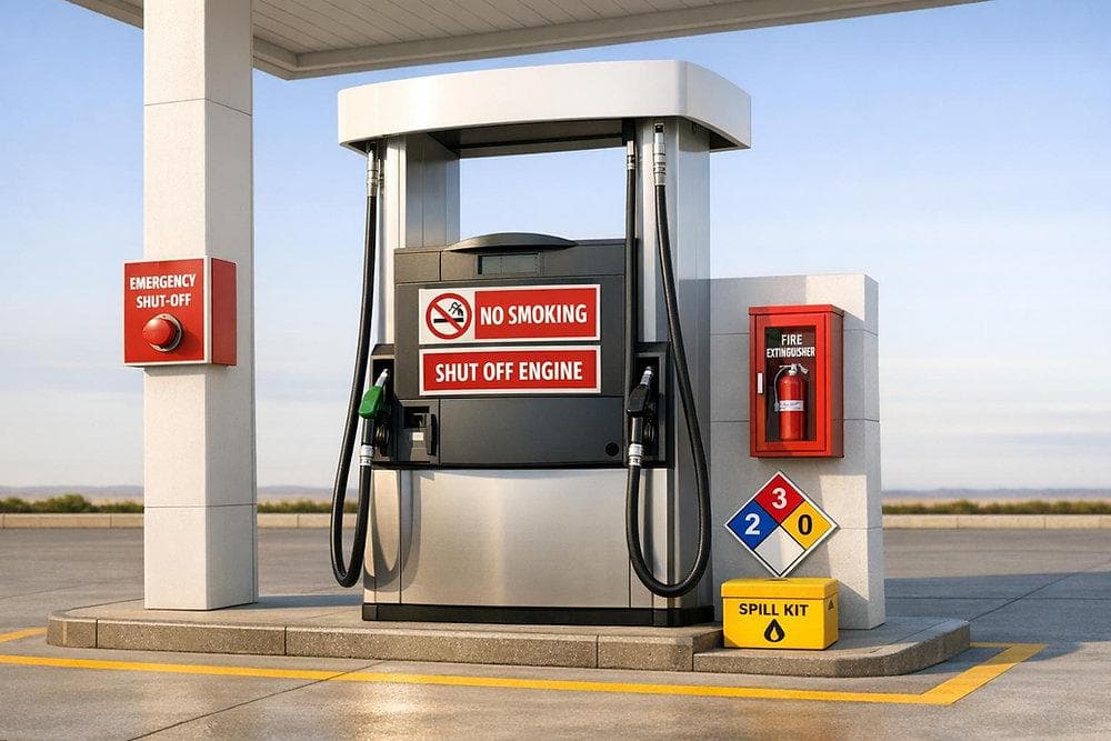
3. Hazardous Areas Around Gasoline Dispensers
Fuel dispensers are another important source of potential gasoline vapor release.
According to GB 50156—2021, the internal space of the lower cabinet of a gasoline dispenser is classified as Zone 1.
The surrounding area is classified as Zone 2 according to the specified geometric limits.
For the standard arrangement, the Zone 2 area is defined using a horizontal radius of 4.5 m around the dispenser centerline, with another specified upper boundary around the lower cabinet. The standard also provides an alternative radius of 3.0 m under the applicable condition.
This means that electrical components installed near a fuel dispenser cannot simply be selected according to whether they are outdoors.
The actual hazardous-area classification must be considered first.
4. Explosion-Proof Electrical Equipment
Once hazardous areas have been classified, electrical equipment installed within those areas must be selected according to the applicable explosion-protection requirements.
GB 50156—2021 requires electrical equipment, installation and power-line routing within explosive hazardous areas to comply with GB 50058 and other applicable standards.
Typical equipment requiring careful selection includes:
- Explosion-proof junction boxes
- Explosion-proof switches
- Explosion-proof lighting
- Explosion-proof motors
- Explosion-proof control equipment
- Explosion-proof cable glands
- Explosion-proof electrical enclosures
- Explosion-proof gas detectors where applicable
The important principle is:
Do not select electrical equipment first and classify the area afterward.
The correct sequence should be:
Hazardous Area Classification → Equipment Protection Level → Installation Method → Inspection and Maintenance
5. Electrical Cable and Installation Requirements
Cable installation is also an important part of explosion protection.
Proper underground fuel piping and cable routing should also be considered together during station construction.
GB 50156—2021 states that cables at gas stations should generally be installed by direct burial or inside protective conduits.
Where cables cross vehicle traffic lanes, they should be protected by steel pipes.
In addition, cable trenches located within the operating area must be filled with sand when the cable-trench method is used.
Cables should not share the same trench with oil, gas, LPG, LNG, CNG or heating pipelines.
These measures reduce the possibility of mechanical damage, vapor accumulation and unsafe interaction between electrical and fuel systems.
6. Combustible Gas Detection
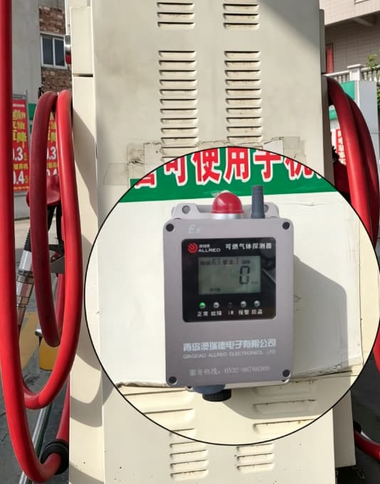
Combustible gas detection is another important safety measure, but its application depends on the type of gas station and the equipment installed.
GB 50156—2021 specifically requires combustible gas detectors in certain LPG, LNG, CNG and hydrogen facilities. For example, detectors are required in specified outdoor LPG/LNG equipment areas and in rooms, cabinets and canopies containing CNG or hydrogen-related equipment.
The standard specifies that the first-level alarm setting should be no higher than 25% of the lower explosive limit (LEL) for these applicable facilities.
For a gasoline station, the use of combustible-vapor detection should therefore be determined according to the station design, fuel type, equipment arrangement, applicable local regulations and risk assessment rather than simply assuming that every gasoline station must install the same detector.
Practical protection measures include:
- Installing detectors at appropriate potential vapor accumulation points
- Using equipment suitable for the hazardous area
- Linking alarms with ventilation or emergency shutdown systems where required
- Performing regular calibration and functional testing
- Keeping detection sensors unobstructed
- Maintaining records of inspection and calibration
7. Ventilation in Hazardous Areas
Ventilation is important because preventing the accumulation of flammable vapor reduces the possibility of forming an explosive atmosphere.
For applicable hazardous-area rooms or enclosures, GB 50156—2021 requires ventilation measures.
Where mechanical ventilation is used, the standard specifies a ventilation capacity of:
12 air changes per hour during equipment operation
and
5 air changes per hour when the equipment is not operating.
The ventilation equipment should be explosion-proof and interlocked with the combustible gas concentration alarm system where the standard applies.
This illustrates an important engineering principle:
Explosion protection is not only about selecting explosion-proof electrical equipment. Vapor control and ventilation are equally important.
8. Practical Explosion-Protection Measures
A complete gas station explosion-protection strategy should combine several measures.
1. Control the release of fuel vapor
Use properly sealed:
- Tank manholes
- Unloading connections
- Valves
- Pipe joints
- Vapor recovery connections
2. Prevent vapor accumulation
Provide appropriate:
- Natural ventilation
- Mechanical ventilation
- Vapor recovery systems
- Drainage and containment arrangements
3. Control ignition sources
Keep unsuitable:
- Open flames
- Hot surfaces
- Sparks
- Non-explosion-proof electrical equipment
away from hazardous areas.
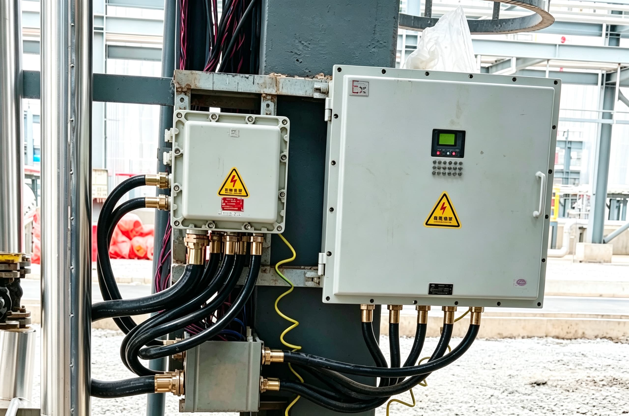
4. Select suitable electrical equipment
Electrical equipment installed inside hazardous areas should have protection suitable for the classified zone and the actual gas/vapor characteristics.
5. Protect cables and connections
Use suitable:
- Conduits
- Cable glands
- Junction boxes
- Sealing fittings
- Grounding and bonding arrangements
6. Install monitoring and alarm systems where required
Gas detection and alarm systems should be selected according to the fuel type, hazardous-area classification and applicable regulations.
Need help selecting explosion-proof gas station equipment and related components? Contact our team to discuss your project requirements.
9. Hazardous Area Classification Example
A simplified gasoline station can be understood through the following relationship:
Underground Tank
→ Tank internal vapor space: Zone 0
→ Tank manhole / valve chamber: Zone 1
→ Areas around vent and unloading connections: Zone 1 / Zone 2 according to the specified boundaries
→ Fuel dispenser lower cabinet: Zone 1
→ Area surrounding the dispenser: Zone 2 according to the specified boundaries
This classification provides the basis for selecting electrical equipment and designing safe installation arrangements.
However, the actual classification should always be determined from the applicable standard drawings, equipment configuration and project conditions rather than using a simplified diagram as the final engineering basis.
10. Key Data at a Glance
| Item | Requirement / Reference |
|---|---|
| Hazardous zones | Zone 0, Zone 1, Zone 2 |
| Tank internal vapor space | Zone 0 |
| Tank manhole/valve chamber | Zone 1 |
| Gasoline dispenser lower cabinet | Zone 1 |
| Typical tank vent Zone 2 radius | 3.0 m / 2.0 m according to specified condition |
| Closed unloading connection Zone 2 radius | 1.5 m |
| Gasoline dispenser Zone 2 radius | 4.5 m / 3.0 m according to specified condition |
| Applicable detector first-level alarm for specified LPG/LNG/CNG/H₂ facilities | ≤25% LEL |
| Mechanical ventilation during operation, where applicable | 12 air changes/hour |
| Mechanical ventilation when not operating, where applicable | 5 air changes/hour |
The numerical values above are based on the cited provisions of GB 50156—2021 and GB 50058—2014; project-specific designs should use the applicable standard drawings and requirements.
11. Conclusion
Hazardous area classification is one of the foundations of gas station safety design.
The basic principle is to first determine where flammable vapor may exist, then classify the area as Zone 0, Zone 1 or Zone 2, and finally select suitable electrical equipment, cable installation methods, ventilation, monitoring and other protective measures.
For gasoline stations, special attention should be given to:
- Underground tank manholes
- Tank vent outlets
- Fuel unloading connections
- Fuel dispensers
- Vapor recovery equipment
- Valves and pipe connections
A properly designed system should combine hazardous-area classification, explosion-proof electrical equipment, vapor control, ventilation, gas detection where applicable, grounding and regular inspection rather than relying on a single safety measure.
For a new gas station project, equipment selection should be coordinated with the site layout and hazardous-area classification from the beginning.
Contact Us
Planning a new gas station or upgrading an existing fuel station?
Xing Zhong Yuan provides gas station equipment and supply chain support, including fuel dispensers, submersible pumps, underground fuel tanks, piping components, vapor recovery equipment and related accessories.
Contact us to discuss your project requirements and equipment configuration.