
PV Valve Working Principle: How to Size a Pressure Vacuum Valve for Fuel Tanks
News 2026年 9月 11日 91
Introduction
A fuel storage tank cannot be completely sealed.
When fuel enters the tank, vapor space pressure increases. When fuel is withdrawn, the vapor space pressure decreases. Temperature changes can also cause the vapor inside the tank to expand or contract.
A pressure vacuum valve (PV valve) provides controlled breathing for the tank by releasing vapor when pressure becomes too high and allowing air to enter when vacuum becomes too high.
But for fuel station projects, the more important question is not simply “What is a PV valve?”
The real question is:
How do you determine the required venting capacity, pressure setting, and vacuum setting for a fuel storage tank?
This article explains the PV valve working principle, the main factors affecting PV valve sizing, and how to evaluate a pressure vacuum valve for a fuel tank using practical engineering calculations.
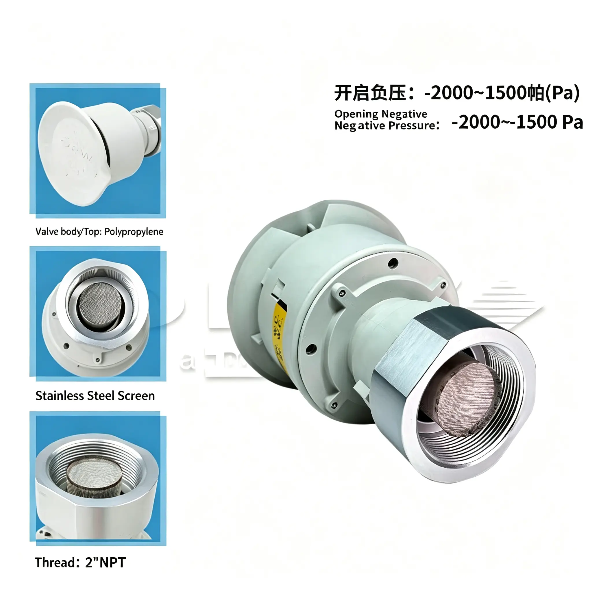
1. How Does a PV Valve Work?
A PV valve normally contains two basic functions:
- Pressure relief
- Vacuum relief
The valve remains closed during normal tank operation. When tank pressure reaches the preset pressure value, the pressure side opens and allows vapor to escape.
When tank pressure falls below the preset vacuum value, the vacuum side opens and allows air to enter.
The basic operating process is:
Fuel filling → vapor volume decreases → tank pressure rises → pressure side opens
Fuel dispensing → vapor volume increases → tank pressure falls → vacuum side opens
Temperature rises → vapor expands → pressure may increase
Temperature falls → vapor contracts → vacuum may develop
Therefore, a fuel tank vent valve is not simply an outlet pipe. It is part of the tank’s pressure and vacuum protection system.
2. Why Does a Fuel Tank Need a Pressure Vacuum Valve?
A fuel tank experiences several different breathing conditions during normal operation.
2.1 Fuel Withdrawal
When fuel leaves the tank, the liquid level decreases and the vapor space becomes larger.
If the tank does not receive enough replacement air, negative pressure can develop.
For example, using the published API 2000 calculation approach for normal inbreathing:
Vᵢ = 8.02 × Q
Where:
- Vᵢ = required inbreathing capacity, SCFH
- Q = maximum liquid withdrawal rate, US gal/min
For a 100 GPM withdrawal rate:
Vᵢ = 8.02 × 100 = 802 SCFH
For 200 GPM:
Vᵢ = 8.02 × 200 = 1,604 SCFH
This shows why the maximum fuel withdrawal rate is an important input when determining PV valve sizing.
3. Fuel Filling and Tank Outbreathing
The opposite condition occurs when fuel is pumped into the tank.
As liquid enters the tank, the available vapor space decreases. Vapor and displaced gas therefore need a path to leave the tank.
For volatile liquids, the published API 2000 calculation approach gives the normal outbreathing component as:
Vₒ = 16.04 × Q
Where:
- Vₒ = required outbreathing capacity, SCFH
- Q = maximum liquid filling rate, US gal/min
For a 100 GPM filling rate:
Vₒ = 16.04 × 100 = 1,604 SCFH
For 200 GPM:
Vₒ = 16.04 × 200 = 3,208 SCFH
The difference is important.
At the same 100 GPM liquid flow rate:
| Condition | Calculation | Venting Component |
|---|---|---|
| Liquid withdrawal | 8.02 × 100 | 802 SCFH |
| Volatile liquid filling | 16.04 × 100 | 1,604 SCFH |
Therefore, PV valve sizing cannot be based only on the tank capacity.
The filling and withdrawal rates must also be considered.
4. Thermal Breathing Can Also Affect PV Valve Sizing
Fuel movement is not the only source of tank breathing.
Temperature changes can cause the vapor space inside the tank to expand or contract.
For example:
Daytime heating → vapor expands → outbreathing
Nighttime cooling → vapor contracts → inbreathing
This is generally referred to as thermal breathing or thermal venting.
API 2000 treats normal tank venting as a combination of effects associated with liquid movement and thermal changes. Tank volume, vapor-space volume, temperature variation, insulation, operating conditions and other factors can affect the required venting capacity.
This means a simple calculation based only on:
Tank capacity × fuel flow rate
is not sufficient for every project.
For larger tanks or projects with significant temperature variation, thermal effects should be evaluated as part of the overall tank venting calculation.
Need help checking the required venting capacity? Send us your tank capacity and maximum filling and withdrawal rates.
5. PV Valve Sizing Example
Let’s look at a practical fuel station example.
Assume a tank system has:
- Maximum fuel filling rate: 100 GPM
- Maximum fuel withdrawal rate: 100 GPM
Inbreathing calculation
Using:
Vᵢ = 8.02 × Q
We get:
8.02 × 100 = 802 SCFH
So the liquid withdrawal component is approximately:
802 SCFH
Outbreathing calculation
Using:
Vₒ = 16.04 × Q
We get:
16.04 × 100 = 1,604 SCFH
So the volatile-liquid filling component is approximately:
1,604 SCFH
If the maximum flow increases to 200 GPM:
| Maximum Flow | Inbreathing | Outbreathing |
|---|---|---|
| 50 GPM | 401 SCFH | 802 SCFH |
| 100 GPM | 802 SCFH | 1,604 SCFH |
| 200 GPM | 1,604 SCFH | 3,208 SCFH |
| 300 GPM | 2,406 SCFH | 4,812 SCFH |
The table makes one point very clear:
Higher fuel flow rates require significantly higher tank venting capacity.
These figures represent the liquid-movement components of the published API 2000 calculation approach. The final project venting requirement should also consider applicable thermal effects and the requirements of the current edition of the applicable standard.
6. Why Vent Pipe Size Alone Cannot Determine PV Valve Size
A common mistake during fuel station equipment selection is to look only at the vent pipe connection.
For example, a buyer may ask:
“The tank has a 2-inch vent pipe. Do I need a 2-inch PV valve?”
The answer is not automatically yes.
A PV valve has at least three separate considerations:
- Connection size
- Pressure/vacuum setting
- Actual venting capacity
A larger connection does not automatically mean the valve provides the required venting performance.
Likewise, a valve with the correct connection diameter may still be unsuitable if its pressure or vacuum setting does not match the tank design.
Therefore, PV valve sizing should be based on the tank’s actual operating requirements rather than connection size alone.
7. PV Valve Pressure Setting
The pressure setting determines approximately when the pressure side of the valve begins to open.
For example, pressure may be specified in:
- inches of water column (in. WC)
- Pa
- kPa
- mbar
A useful conversion is:
1 in. WC ≈ 249 Pa
Therefore:
| Pressure | Approximate SI Value |
|---|---|
| 1 in. WC | 249 Pa |
| 2 in. WC | 498 Pa |
| 4 in. WC | 996 Pa |
| 6 in. WC | 1.49 kPa |
| 10 in. WC | 2.49 kPa |
The correct PV valve pressure setting should not simply be selected from the valve catalog.
It needs to be compatible with:
- Tank design pressure
- Tank construction
- Venting system
- Fuel characteristics
- Operating conditions
- Applicable project standards
A pressure setting that is too high may allow excessive tank pressure before relief.
A setting that is too low may cause unnecessary venting during normal operation.
8. PV Valve Vacuum Setting
The vacuum side works in the opposite direction.
When fuel leaves the tank or the vapor cools, the tank pressure may fall below atmospheric pressure.
The vacuum side of the valve opens when the negative pressure reaches the specified setting.
Vacuum may be expressed as:
- in. WC
- Pa
- kPa
- mbar
For example:
2 in. WC ≈ 498 Pa
6 in. WC ≈ 1.49 kPa
The correct PV valve vacuum setting must be compatible with the tank’s allowable vacuum.
This is particularly important because underground storage tanks and other fuel tanks are not designed to withstand unlimited external pressure.
Therefore:
The PV valve should protect the tank without creating an operating range that conflicts with the tank’s design limits.
9. Common PV Valve Problems
Even if the original valve selection is correct, the system can still develop problems if the valve is poorly installed or maintained.
PV Valve Leaking
A PV valve leaking problem may be associated with:
- Damaged sealing surfaces
- Dirt or deposits
- Incorrect pressure setting
- Foreign material
- Corrosion
- Improper installation
- Valve damage
Continuous vapor release should not simply be treated as a normal operating condition.
The valve should be checked against its specified pressure setting and operating conditions.
PV Valve Not Working
If a PV valve is not working, possible causes include:
- Stuck pressure disc
- Stuck vacuum disc
- Blocked vent passage
- Contamination
- Incorrect installation
- Incorrect pressure/vacuum setting
- Mechanical damage
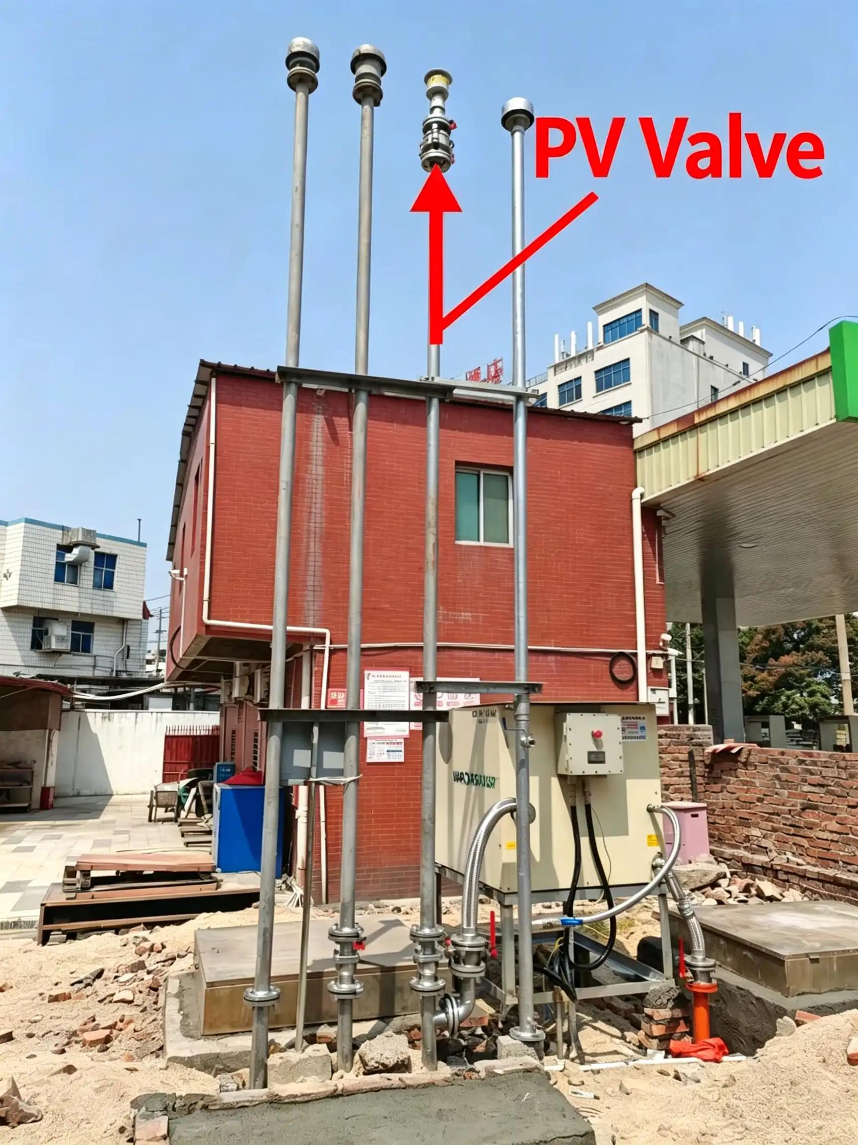
For underground fuel storage systems, PV valve inspection should also be considered together with the tank, vent piping and leak detection system.
The same principle applies when checking the complete underground fuel piping system.
10. PV Valve vs. Emergency Vent
A PV valve and an emergency vent are not necessarily the same device.
A normal PV valve is designed to control pressure and vacuum during normal tank breathing.
An emergency venting device is intended to address abnormal or emergency conditions that can create much larger pressure loads.
This distinction is important when preparing a fuel tank venting system.
A project may require:
- Normal pressure relief
- Normal vacuum relief
- Emergency venting
- Vapor recovery
- Vent piping
- Tank monitoring
- Leak detection
The complete system should therefore be evaluated rather than selecting a single valve in isolation.
11. How to Select a PV Valve for a Fuel Tank
Before purchasing a pressure vacuum valve for a fuel tank, collect the following information.
1. Tank capacity
Example:
- 20 m³
- 30 m³
- 50 m³
- 60 m³
- 100 m³
2. Fuel type
For example:
- Gasoline
- Diesel
- Ethanol-containing fuel
- Other petroleum products
Fuel characteristics can affect vapor generation and venting requirements.
3. Maximum filling rate
Do not use the average daily fuel volume.
The calculation should consider the maximum instantaneous filling rate.
4. Maximum withdrawal rate
Consider the maximum fuel dispensing demand.
If several fuel dispensers operate simultaneously, the combined flow rate may be important.
5. Vent pipe configuration
Check:
- Pipe diameter
- Pipe length
- Number of bends
- Fittings
- Vapor recovery arrangement
- Discharge location
6. Pressure setting
Confirm the required positive pressure range.
7. Vacuum setting
Confirm the allowable negative pressure range.
8. Required venting capacity
The valve’s actual flow capacity must be sufficient for the calculated requirement.
This is why PV valve flow rate and PV valve venting capacity should be checked together with the pressure and vacuum settings.
Not sure which PV valve configuration fits your tank? Send us the tank and venting parameters for a configuration check.
12. Where a PV Valve Fits into a Fuel Station Equipment Package
A PV valve is only one component of the overall fuel storage and dispensing system.
A typical project may also require:
- Fuel dispensers
- Submersible pumps or pumping systems
- Underground fuel piping
- Tank accessories
- Vent piping
- Vapor recovery equipment
- Leak detection equipment
- Liquid level monitoring systems
- Other fuel station equipment
For overseas projects, the challenge is often not finding one individual component.
The more difficult part is making sure the different components are compatible with the project requirements and can be sourced and coordinated correctly.
This is where a gas station equipment supply chain service provider can be useful.
Instead of selecting each component separately, the project can be reviewed from the perspective of tank requirements, piping, venting, dispensing and related equipment.
13. Final PV Valve Selection Checklist
Before placing an order, check these parameters:
| Parameter | What to Confirm |
|---|---|
| Tank capacity | Total tank volume |
| Fuel type | Gasoline, diesel or other fuel |
| Filling rate | Maximum GPM or L/min |
| Withdrawal rate | Maximum GPM or L/min |
| Vent pipe | Diameter and configuration |
| Pressure setting | Required positive pressure |
| Vacuum setting | Required negative pressure |
| Venting capacity | Required SCFH or equivalent |
| Installation | Tank/vent piping arrangement |
| Environment | Temperature and operating conditions |
| Standards | Applicable local/project requirements |
A valve should not be selected simply because:
“The connection size looks correct.”
The more important question is:
Can the valve provide the required pressure and vacuum protection at the required venting capacity under the actual tank operating conditions?
14. Need Help Selecting a PV Valve for Your Fuel Tank?
Choosing a PV valve is not only about the connection size.
The required venting capacity depends on the tank capacity, fuel type, maximum filling rate, maximum withdrawal rate, vent pipe configuration, and required pressure/vacuum settings.
If you are sourcing PV valves for a new gas station, tank replacement, or equipment project, send us the following information:
- Tank capacity
- Fuel type
- Maximum filling rate
- Maximum withdrawal rate
- Vent pipe size
- Required pressure and vacuum settings
- Project country
We can help you check the basic configuration and coordinate the appropriate fuel tank vent valve and related gas station equipment according to your project requirements.
Request a PV Valve Quote
Send us your tank parameters and project requirements for a basic configuration check and quotation.