
Gas Station Underground Fuel Piping: Pipe Size, Layout and Installation Guide
News 2026年 8月 15日 65
Introduction
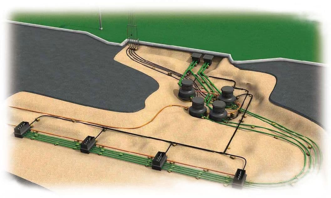
Underground fuel piping connects the storage tank, submersible pump and fuel dispensers. Its design directly affects fuel flow, pressure loss, vapor recovery, leak detection and long-term system reliability.
For projects applying GB 50156-2021, important parameters include pipe wall thickness, burial depth, pipeline slope, double-wall construction, vapor recovery pipe diameter and tank connection dimensions.
This guide focuses on the engineering values that are most useful when selecting and installing underground fuel piping.
Important: The numerical values in this article are based mainly on the cited Chinese requirements and engineering references. International projects should also comply with the applicable local fire, environmental, petroleum-storage and construction codes.
1. What Is Underground Fuel Piping?
A typical fuel delivery system is:
Underground Fuel Tank → Submersible Pump → Main Fuel Pipe → Branch Pipe → Fuel Dispenser → Nozzle
Depending on the station design, the underground piping system may also include:
- Fuel unloading pipes
- Dispensing pipes
- Unloading vapor recovery pipes
- Dispensing vapor recovery pipes
- Tank vent pipes
- Double-wall piping
- Leak detection systems
The piping system should be designed together with the tank, pump and dispenser rather than selected separately.
2. Single-Wall vs. Double-Wall Fuel Piping
For underground fuel dispensing pipelines under the cited Chinese requirements, double-wall piping is required.
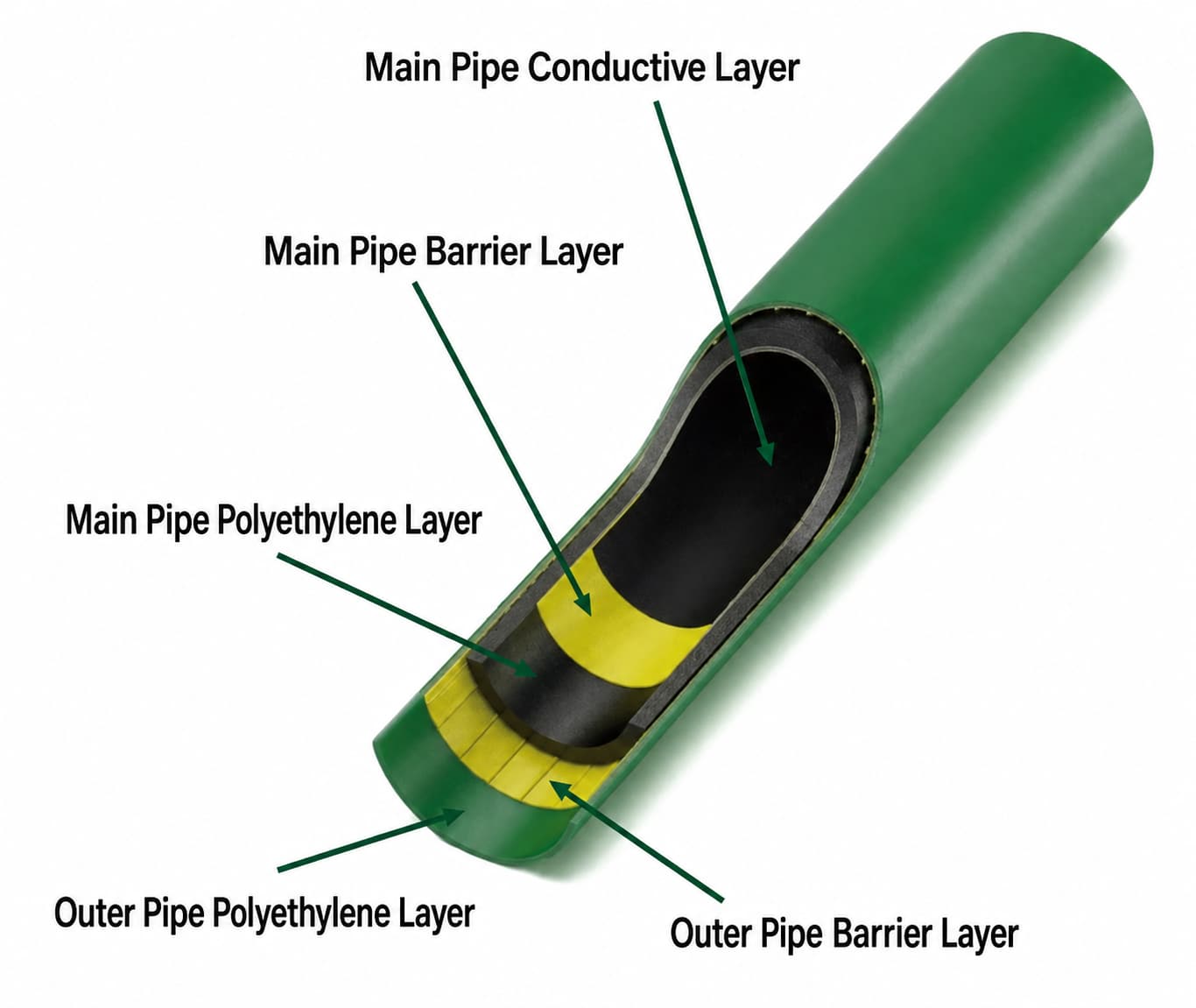
A double-wall system consists of:
Inner Fuel Pipe → Interstitial Space → Outer Pipe
The interstitial space should be continuous and connected to a suitable leak detection point.
For double-wall steel piping, the cited requirement specifies an outer pipe wall thickness of approximately 5 mm or more.
The double-wall dispensing pipe should generally slope toward the leak detection point at:
≥ 5‰
This is important because the interstitial space needs to guide leaked liquid toward the detection point rather than allowing liquid to remain trapped underground.
For projects using online leak monitoring, the detection system should be compatible with the double-wall pipe structure and monitoring arrangement.
Tank level and leakage monitoring can be integrated through a [Fuel Tank Level Monitoring System].
3. Fuel Pipe Material and Wall Thickness
The appropriate pipe material depends on fuel type, pressure, installation method, temperature, corrosion conditions and local regulations.
Common materials include:
- Seamless steel pipe
- Fuel-compatible thermoplastic pipe
- Conductive thermoplastic pipe for applicable fuel systems
- Austenitic stainless steel for DEF or other special fluids
For the cited requirements:
| Parameter | Reference Value |
|---|---|
| Seamless steel pipe wall thickness | ≥ 4 mm |
| Thermoplastic structural layer | ≥ 4 mm |
| Buried steel pipe joints | Welded |
| Buried thermoplastic joints | Electrofusion |
| Conductive thermoplastic volume resistivity | < 10⁸ Ω·m |
| Conductive thermoplastic surface resistivity | < 10¹⁰ Ω |
For non-conductive thermoplastic piping, the cited requirement also specifies a dielectric breakdown strength above 100 kV.
For non-static-dissipative thermoplastic sections, the fuel flow velocity should remain below approximately:
2.8 m/s
This is particularly important for short exposed sections inside tank manholes, dispenser sumps and unloading areas.
4. How to Choose Underground Fuel Pipe Diameter
There is no universal pipe diameter based only on the number of dispensers.
Pipe diameter should be determined from the complete hydraulic system.
The main parameters are:
| Parameter | Effect |
|---|---|
| Fuel flow rate | Determines required capacity |
| Number of nozzles | Determines potential demand |
| Simultaneous fueling | Determines peak flow |
| Pipe length | Affects friction loss |
| Pipe diameter | Affects velocity and pressure loss |
| Number of elbows | Adds fitting resistance |
| Elevation difference | Affects required pump head |
| Pump performance | Determines available flow and pressure |
A simplified relationship is:
Required Pump Head = Static Head + Pipe Friction Loss + Fitting Loss + Required Outlet Pressure
For example, if three nozzles may operate simultaneously and each requires approximately 40 L/min:
3 × 40 = 120 L/min
This gives an initial flow requirement of approximately 120 L/min before considering pressure losses and operating margin.
Therefore, the pump and pipeline should always be selected as one hydraulic system.
For more information, see our [Gas Station Submersible Pump Selection Guide].
5. How Many Dispensers Can One Submersible Pump Supply?
One submersible pump can supply multiple dispensers or nozzles, but there is no universal rule such as “one pump = three dispensers.”
The actual configuration depends on:
- Pump flow capacity
- Pump head
- Number of nozzles
- Simultaneous fueling demand
- Main pipe diameter
- Branch pipe diameter
- Pipeline length
- Elevation difference
- Dispenser flow requirement
For example:
1 Pump → 2 Dispensers → 4 Nozzles
or
1 Pump → 3 Dispensers → 6 Nozzles
may both be possible, provided the pump and piping have sufficient capacity.
The important calculation is not simply the number of dispensers, but the maximum simultaneous flow demand.
6. Underground Fuel Pipe Burial Depth
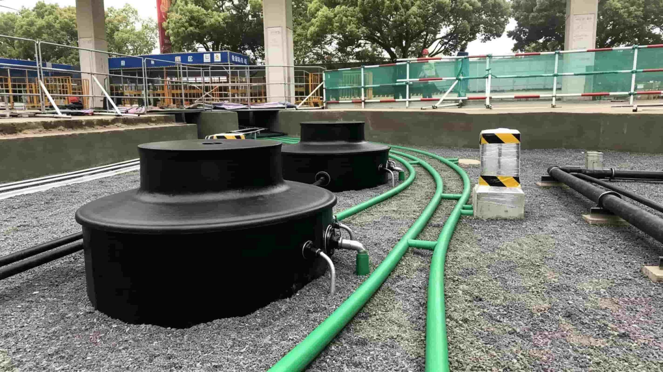
For projects applying the cited Chinese requirements, underground process piping should have:
| Installation Condition | Reference Requirement |
|---|---|
| Minimum underground burial depth | ≥ 0.4 m |
| Pipe top below underside of concrete/road layer | ≥ 0.2 m |
| Neutral sand/fine soil around pipe | ≥ 100 mm |
The 0.4 m value should not be confused with underground tank burial depth.
Where piping is installed below concrete or vehicle traffic areas, the vertical relationship between the pipe and concrete structure must also be considered.
Around the buried pipe, at least 100 mm of suitable neutral sand or fine soil should be provided under the cited requirement.
7. Underground Fuel Piping Slope Requirements
Different pipelines have different slope requirements. They should not all be designed using the same slope.
For the cited requirements:
| Pipeline | Minimum Slope | Direction |
|---|---|---|
| Fuel unloading pipe | ≥ 2‰ | Toward tank |
| Unloading vapor recovery pipe | ≥ 1‰ | Toward tank |
| Dispensing vapor recovery pipe | ≥ 1‰ | Toward tank |
| Tank vent horizontal pipe | ≥ 1‰ | Toward tank |
| Double-wall dispensing pipe | ≥ 5‰ | Toward leak detection point |
Important Correction
The vapor recovery and tank vent horizontal pipe slope is 1‰, not 1%.
The difference is significant:
1% = 10‰
Using 1% where 1‰ is required would create a slope ten times steeper than the cited minimum.
Where site conditions make the dispensing vapor recovery pipe slope difficult to maintain, a vapor collector can be arranged near the tank, with the relevant collector section designed with a slope of approximately:
≥ 1%
This should be treated as a special layout solution rather than the normal slope for all vapor recovery piping.
8. Fuel Unloading and Vapor Recovery Piping
Fuel unloading should use a closed connection system.
For gasoline stations, the unloading system should be designed together with vapor recovery.
Unloading Connection
Each storage tank should normally have its own:
- Fuel unloading pipe
- Unloading connection
- Clearly identified connection point
The unloading interface should use a:
Quick coupling + sealing cap
The unloading and vapor recovery connections should be clearly marked to avoid incorrect connection during tanker unloading.
Unloading Vapor Recovery
For gasoline systems using balanced vapor recovery:
Unloading vapor recovery main pipe nominal diameter ≥ 100 mm
The connection should use a self-closing quick connector and sealing cap where applicable.
Unloading vapor recovery hoses should be fuel-resistant and conductive.
Reference electrical properties include:
- Volume resistivity < 10⁸ Ω·m
- Surface resistivity < 10¹⁰ Ω
9. Dispensing Vapor Recovery Piping
Gasoline stations equipped with dispensing vapor recovery normally use a vacuum-assisted system.
The recovered vapor is returned from the dispenser to the underground tank through dedicated vapor recovery piping.
The cited requirements specify:
Dispensing vapor recovery main pipe nominal diameter ≥ 50 mm
The system should also prevent vapor from flowing back toward the nozzle.
For vapor recovery dispensers, the gas-liquid ratio should generally be controlled within:
1.0–1.2
A threaded tee should also be provided at the dispenser bottom/riser where required for liquid restriction and tightness testing.
A typical test branch can use:
25 mm ball valve + plug
This provides a practical connection point for testing and commissioning.
10. Tank Connections and Internal Pipe Positions
The connection between underground piping and the tank is another area where dimensional details matter.
Under the cited requirements:
Fuel Filling Pipe
The filling pipe should extend to approximately:
50–100 mm above the tank bottom
The pipe bottom can use a suitable angled or T-type outlet arrangement to reduce direct impact on the tank bottom.
The filling arrangement should also prevent the opening from directly communicating with the tank vapor space.
Submersible Pump Inlet
The submersible pump inlet should be approximately:
150–200 mm above the tank bottom
This dimension must be considered when selecting the pump length and installation assembly.
Tank Gauge Pipe
The gauge pipe should extend to approximately:
200 mm above the tank bottom
A suitable equalization arrangement should also be provided where required.
Manhole Connections
Tank-top piping and equipment should be arranged so that the manhole cover can still be removed for maintenance.
A flexible metal hose transition between the manhole cover and external piping can help accommodate installation and maintenance requirements.
Planning a Complete Underground Fuel System?
We can help coordinate underground fuel tanks, submersible pumps, fuel piping, vapor recovery systems, level monitoring and fuel dispensers according to your project requirements.
11. Tank Vent Pipe Requirements
Gasoline and diesel tank vent pipes should be arranged separately.
For the cited requirements:
| Parameter | Reference Value |
|---|---|
| Tank vent pipe nominal diameter | ≥ 50 mm |
| Vent outlet height above ground | ≥ 4 m |
| Outlet near building wall/column | ≥ 2 m above building top |
| Flame protection | Flame arrester required |
For gasoline stations with vapor recovery, the vent system should also be equipped with a pressure/vacuum valve.
Reference working pressure ranges are:
- Positive pressure: 2–3 kPa
- Negative pressure: 1.5–2 kPa
The vent system must be designed together with the tank, vapor recovery system and environmental conditions rather than treated as a simple exhaust pipe.
12. Pipe Length, Diameter and Pump Matching
Pipeline length directly affects pressure loss.
A simplified comparison is:
Short Pipe → Lower Friction Loss → Lower Required Pump Head
Long Pipe → Higher Friction Loss → Higher Required Pump Head
Pipe diameter also has a major effect.
A smaller diameter generally produces:
- Higher flow velocity
- Higher friction loss
- Greater pressure drop
A larger diameter can reduce pressure loss but may increase material and installation costs.
Before selecting a submersible pump, provide:
- Tank location
- Dispenser location
- Pipeline length
- Pipe diameter
- Number of branches
- Number of elbows
- Elevation difference
- Required flow rate
- Fuel type
This information allows the pump performance curve to be matched to the actual piping system.
13. Common Underground Fuel Piping Problems
Problem 1: Selecting Pipe Diameter Only by Dispenser Quantity
Two stations may have the same number of dispensers but completely different pipe lengths and flow requirements.
Better approach: Calculate simultaneous flow demand and consider pressure loss.
Problem 2: Using 1% for All Vapor Recovery Pipes
This can result from confusing 1‰ with 1%.
Better approach: Use the pipeline-specific slope values.
Problem 3: Ignoring Vapor Recovery Pipe Diameter
A fuel pipe may be correctly sized while the vapor recovery system remains undersized.
Reference values:
- Unloading vapor recovery main: ≥100 mm
- Dispensing vapor recovery main: ≥50 mm
Problem 4: Selecting the Pump Before Designing the Pipeline
A high-power pump cannot compensate for an incorrectly designed pipeline.
Better approach:
Tank → Pump → Pipeline → Dispenser
should be evaluated as one complete system.
Problem 5: Ignoring Static Dissipation
Thermoplastic fuel piping and flexible hoses must be selected according to the applicable static-dissipation requirements.
For conductive thermoplastic:
Volume resistivity <10⁸ Ω·m
Surface resistivity <10¹⁰ Ω
14. Underground Fuel Piping Installation Checklist
Before ordering or installing the system, confirm:
| Parameter | Check |
|---|---|
| Fuel type | Gasoline / Diesel / DEF |
| Tank capacity | m³ |
| Number of dispensers | Units |
| Number of nozzles | Units |
| Simultaneous fueling | Nozzles |
| Required flow | L/min |
| Main pipe diameter | Project-specific |
| Branch pipe diameter | Project-specific |
| Pipeline length | m |
| Number of elbows | pcs |
| Elevation difference | m |
| Pipe material | Steel / Thermoplastic |
| Pipe wall thickness | ≥4 mm where applicable |
| Burial depth | ≥0.4 m where applicable |
| Backfill around pipe | ≥100 mm |
| Double-wall piping | According to project requirements |
| Leak detection | Required where applicable |
| Unloading vapor recovery main | ≥100 mm |
| Dispensing vapor recovery main | ≥50 mm |
| Vent pipe | ≥50 mm |
| Pump flow/head | L/min + m |
Conclusion
Underground fuel piping should be designed as a complete system rather than simply choosing a pipe diameter.
The most important engineering values to remember are:
- ≥4 mm — reference wall thickness for applicable steel and thermoplastic process pipes
- ≥0.4 m — minimum underground process pipe burial depth under the cited Chinese requirement
- ≥0.2 m — pipe top below the underside of concrete/road layer
- ≥100 mm — neutral sand/fine soil around buried pipe
- ≥5‰ — double-wall dispensing pipe slope toward leak detection
- ≥2‰ — fuel unloading pipe slope toward tank
- ≥1‰ — vapor recovery and tank vent horizontal pipe slope
- ≥100 mm — unloading vapor recovery main diameter
- ≥50 mm — dispensing vapor recovery main diameter
- 1.0–1.2 — reference gas-liquid ratio for dispensing vapor recovery
- ≥50 mm — tank vent pipe diameter
- ≥4 m — vent outlet height above ground
- 50–100 mm — fuel filling pipe outlet above tank bottom
- 150–200 mm — submersible pump inlet above tank bottom
- <10⁸ Ω·m — conductive thermoplastic volume resistivity
- <10¹⁰ Ω — conductive thermoplastic surface resistivity
The final pipe configuration should always be checked against the actual tank, pump, dispenser, site layout and local regulations.
Need a Fuel Station Piping Solution?
Send us your fuel type, tank capacity, number of dispensers, required flow rate, pipeline length, pipe diameter, voltage and project location.
Our team can help evaluate the suitable fuel piping, submersible pump and dispenser configuration for your station.