
Gas Station Vapor Recovery System: Testing, Common Issues & Maintenance Guide
News 2026年 8月 3日 65
With stricter environmental regulations and increasing requirements for safety and environmental protection at modern gas stations, gasoline recovery systems have become an essential part of station operations.
During vehicle refueling, gasoline enters the vehicle fuel tank while a large amount of gasoline is generated and displaced from the tank. Without an effective gasoline recovery system, volatile organic compounds (VOCs) can be released directly into the atmosphere.
This not only causes fuel loss and environmental pollution but also increases potential safety risks during gas station operation.
A complete gasoline recovery system is not simply a combination of pipelines. It is an integrated system consisting of mechanical components, electronic control units, sensors, and monitoring equipment.
Among all components, the NP gasoline recovery pump is one of the key power components of the system.
By generating negative pressure, the NP pump provides the driving force for gasoline circulation and adjusts the gasoline recovery volume according to system requirements, helping maintain a stable gas-liquid ratio during refueling.
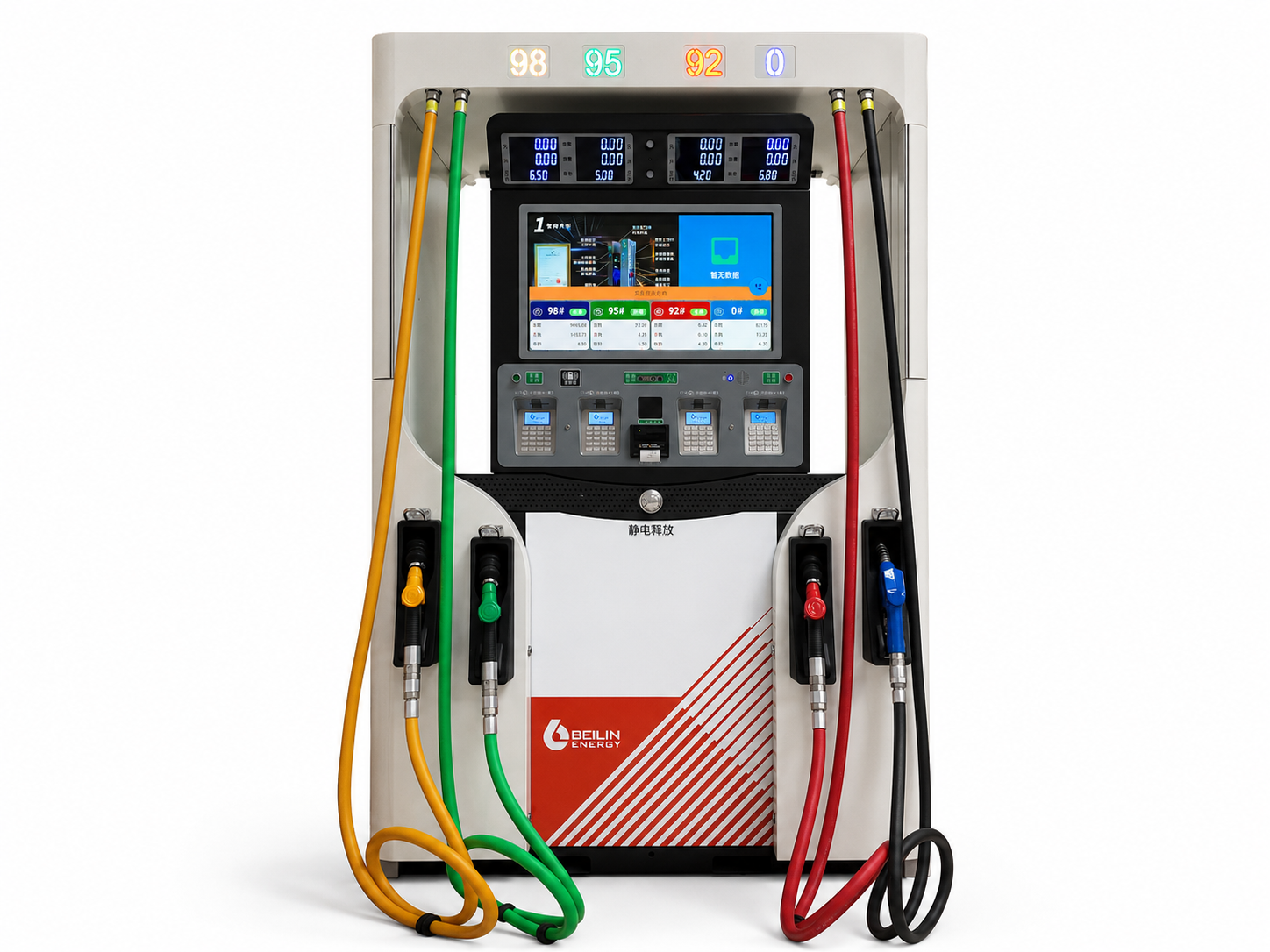
This guide provides a deeper understanding of:
- Gasoline recovery system operation
- NP gasoline recovery pump function
- System testing methods
- Data analysis
- Common problems and troubleshooting
- Daily maintenance requirements
- How Does a Gas Station Gasoline Recovery System Work?
The main purpose of a gasoline recovery system is to collect gasoline generated during vehicle refueling and safely return it through the recovery pipeline to the treatment or storage system.
The basic operating process is:
Vehicle Fuel Tank
↓
Gasoline Recovery Nozzle
↓
Gasoline Return Pipeline
↓
NP gasoline Recovery Pump
↓
Electronic Control System
↓
Gasoline Recovery Tank / Treatment System
During refueling:
Gasoline flows into the vehicle fuel tank, while displaced gasoline is collected through the gasoline recovery nozzle and enters the recovery pipeline.
At this moment, the NP gasoline recovery pump starts operating and creates negative pressure inside the gasoline recovery pipeline, allowing gasoline to be smoothly returned to the recovery system.
At the same time, the control system automatically adjusts the gasoline recovery volume according to the actual fuel dispensing amount, ensuring that the recovered gasoline volume matches the fuel delivery volume.
A properly operating gasoline recovery system can achieve:
- Reduced gasoline emissions
- Lower fuel loss
- Improved environmental performance
- Enhanced gas station safety
- NP Gasoline Recovery Pump — The Core Power Component of the System
Why Is the NP Pump So Important?
The NP gasoline recovery pump is the main power source of the gasoline recovery system.
Its main functions include:
- Generating Negative Pressure
When the NP pump operates, it creates suction inside the gasoline recovery pipeline.
This negative pressure allows gasoline to move from the vehicle fuel tank back into the recovery system.
If the NP pump does not provide enough suction:
Possible results include:
- Reduced gasoline recovery efficiency
- Abnormal gas-liquid ratio
- Unstable system operation
- Controlling Gasoline Recovery Flow
The NP pump does not operate independently.
It works together with:
- Electronic regulating valve
- QK control board
- Gasoline flow detection system
Based on the actual fuel dispensing volume, the system dynamically adjusts the gasoline recovery amount.
This ensures:
The fuel delivery volume and gasoline recovery volume remain within a proper ratio.
- Maintaining a Stable Gas-Liquid Ratio
The gas-liquid ratio is one of the most important performance indicators of a gasoline recovery system.
Required gas-liquid ratio:
0.9~1.3
If the gas-liquid ratio is too low:
Possible issues:
- Insufficient gasoline recovery
- Gasoline cannot be fully collected
- Reduced environmental performance
If the gas-liquid ratio is too high:
Possible issues:
- Excessive gasoline recovery volume
- Unstable system operation
Therefore, proper NP pump adjustment and system commissioning are critical after installation.
- Gasoline Recovery System Testing and Commissioning Requirements
After installation, the gasoline recovery system cannot be put into operation immediately.
Before normal operation, complete testing and commissioning must be performed to confirm:
- Gasoline recovery performance is normal
- NP pump operates correctly
- Gas-liquid ratio meets requirements
- Pressure detection is accurate
- Communication system functions properly
Main testing items include:
- Gasoline recovery flow testing
- Gas-liquid ratio testing
- Pressure sensor testing
- Communication testing
- NP pump operation inspection
Gas-Liquid Ratio Testing
The gas-liquid ratio is one of the most important performance indicators of a gasoline recovery system.
The calculation method is:
Gas-Liquid Ratio = Recovered Gasoline Volume ÷ Dispensed Fuel Volume
System requirement:
Gas-liquid ratio: 0.9~1.3
When the gas-liquid ratio remains within this range, it indicates that the gasoline recovery system is operating normally.
During testing, confirm the following:
✓ Gasoline recovery function of the nozzle is working properly
✓ NP pump operates steadily
✓ Gasoline flow detection is accurate
✓ Gasoline recovery volume matches fuel dispensing volume
When the gas-liquid ratio is abnormal, the following components should be checked:
- NP Pump Adjustment Issue
Check:
- Whether the NP pump starts normally
- Whether the pump rotation direction is correct
- Whether the control signal is working properly
- Gasoline Flow Detection Issue
Check:
- Gasoline flow sensor data
- Signal feedback status
- Accuracy of flow measurement
- Pipeline Problems
Check:
- Whether the gasoline recovery pipeline has leakage
- Whether connections are loose
- Whether the pipeline is blocked
- Electronic Regulating Valve Problems
Check:
- Whether the valve operates correctly
- Whether the control signal is normal
- Gasoline Recovery Data Monitoring and Abnormal Analysis
Modern gasoline recovery systems are usually equipped with online monitoring functions.
Through the monitoring system, operators can check real-time data including:
- Fuel dispensing volume
- Gasoline recovery volume
- Gas-liquid ratio
- Gasoline flow rate
- Maximum gasoline flow rate
- Pressure sensor data
- Communication status
These data help maintenance technicians quickly identify system operating conditions and locate potential problems.
Normal Operating Data Evaluation
Under normal operating conditions:
The gas-liquid ratio should remain:
0.9~1.3
At the same time, attention should be paid to:
- Whether data changes remain stable
- Whether gasoline recovery volume matches fuel dispensing volume
- Whether each nozzle operates normally
If the data changes suddenly, the system should be inspected immediately.
Common Abnormal Data Analysis
Situation 1: Gas-Liquid Ratio Close to 0
Possible causes:
① NP gasoline recovery pump is not operating
② Gasoline flow sensor failure
③ Electronic regulating valve malfunction
④ Gasoline recovery pipeline blockage or leakage
Inspection steps:
Check whether the NP pump starts.
Check:
- NP pump power supply
- Control signal
- Gasoline recovery pipeline
- Flow sensor feedback data
Situation 2: Large Gas-Liquid Ratio Fluctuation
Possible causes:
- Incorrect NP pump adjustment
- Unstable gasoline flow
- Abnormal pressure sensor signal
- System calibration not completed
Check:
- Fuel dispensing flow
- Gasolineflow
- Maximum gasoline flow
- Pressure feedback data
After adjustment, perform another test to ensure the gas-liquid ratio returns to:
0.9~1.3
- Common Gasoline Recovery System Problems and Solutions
A gasoline recovery system consists of mechanical components, electrical components, and control systems.
When a problem occurs, troubleshooting should not focus on only one component. The entire system needs to be checked.
Problem 1: Gas-Liquid Ratio Is 0 or Significantly Low
Possible causes:
- NP pump not working
- Gasoline flow sensor failure
- Electronic regulating valve malfunction
- Gasoline pipeline leakage
Solution:
Check:
✓ NP pump operating condition✓ Power connection
✓ Power connection
✓ Control signal
✓ Pipeline sealing condition
✓ Sensor feedback data
Problem 2: Unstable Gas-Liquid Ratio
Possible causes:
- Incorrect NP pump parameters
- Unstable gasoline flow
- Abnormal sensor signal
- Incomplete system commissioning
Solution:
Check:
- Fuel dispensing flow
- Gasoline flow
- Maximum gasoline flow
- Pressure sensor feedback
After readjustment, perform another test.
Required gas-liquid ratio:
0.9~1.3
Problem 3: Communication Failure Between Devices
The gasoline recovery system involves communication between:
- QK control board
- NP pump control system
- Monitoring system
- Sensors
Possible causes:
- Incorrect RS485 wiring
- Incorrect QK board configuration
- Damaged communication cable
Solution:
Check:
✓ RS485 wiring
✓ Communication address settings
✓ QK board jumper configuration
✓ Signal transmission quality
Problem 4: Abnormal Pressure Sensor Data
The pressure sensor is mainly used to:
Detect pressure changes inside the gasoline recovery pipeline and send feedback signals to the control system.
Possible causes:
- Incorrect installation position
- Loose wiring connection
- Damaged sensor
- Incorrect signal connection
During installation:
The sensor must be connected according to the electrical wiring diagram.
Common connection:
+24V / AD1
After installation:
Confirm that pressure change data can be uploaded correctly.
Need Help Troubleshooting Your Vapor Recovery System?
If you are experiencing abnormal gas-liquid ratios, NP pump problems, sensor errors, communication failures, or unstable system operation, contact our team for technical support and equipment recommendations.
- QK Control Board, RS485 Communication and Multi-Dispenser Configuration
The gasoline recovery system is not a single independent device.
It is a complete control system that combines:
- Mechanical equipment
- Electronic control
- Data communication
- Monitoring functions
The main control components include:
- QK control board
- NP gasoline recovery pump
- Electronic regulating valve
- Gasoline flow detection system
- Pressure sensor
- Online monitoring system
All these components must maintain stable communication and work together to achieve accurate gasoline recovery control.
Function of the QK Control Board
The QK control board is one of the core control modules in the gasoline recovery system.
Its main functions include:
- Receiving sensor signals
- Processing operating data
- Controlling gasoline recovery system operation
- Communicating with the monitoring system
It should be noted that:
The QK control board does not directly control fuel dispensing.
Instead, it achieves accurate gasoline recovery control by coordinating and controlling:
- NP gasoline recovery pump
- Electronic regulating valve
- Gasoline flow detection system
Through this coordinated control, the system can automatically adjust gasoline recovery volume according to actual operating conditions.
RS485 Communication Requirements
For gasoline recovery systems equipped with communication functions:
The RS485 communication system is mainly used for:
- Communication between fuel dispensers
- Connection with gas station management systems
- Uploading gasoline recovery operating data
- Remote monitoring functions
During installation:
The RS485 communication cable must be connected correctly according to the wiring requirements.
Before powering on and testing, confirm:
✓ Communication wiring is correct
✓ Signal transmission is stable
✓ QK control board communication is normal
Important Notice:
The RS485 communication cable must never be connected to:
❌ 380V power lines
❌ 220V power lines
Incorrect wiring may cause:
- Damage to the QK control board
- Damage to the communication module
- Failure of the system to recognize connected devices
Multi-Dispenser Gasoline Recovery System Configuration
For large gas stations:
Multiple fuel dispensers are usually installed.
Each dispenser requires independent:
- NP pump installation
- Communication configuration
- Control board setup
- Gasoline recovery performance testing
Commissioning the First Dispenser
After installation, complete the following:
✓ Install the NP gasoline recovery pump
✓ Connect the RS485 communication line
✓ Configure the QK control board
✓ Test gasoline recovery performance
Confirm:
- All nozzles communicate normally
- System operation is stable
- Gas-liquid ratio remains:
0.9~1.3
Configuration of the Second and Additional Dispensers
After the first dispenser operates normally:
The following dispensers can be configured using the same procedure.
Key points to check:
- QK control board jumper settings
- Dispenser ID configuration
- RS485 communication status
- Operation of each nozzle
Different QK control board models may use different jumper configurations.
Examples:
- QK1000A
- QK1000B
The jumper settings must follow the corresponding wiring diagram.
Incorrect configuration may result in:
- Communication failure
- Control system unable to recognize equipment
- Gasoline recovery function failure
- Electrical Installation Requirements for Gasoline Recovery Systems
Electrical installation is a critical part of ensuring safe and reliable gasoline recovery system operation.
Because gasoline creates a flammable environment, all electrical installation work must comply with explosion-proof requirements.
Incorrect electrical installation may cause:
- Communication failures
- Signal loss
- Control abnormalities
- Reduced explosion-proof protection
Therefore, all wiring connections must strictly follow the equipment electrical drawings.
Power Supply Requirements
Fuel dispenser power requirements:
Three-phase four-wire 380V power supply
Each dispenser must be equipped with:
- Independent control switch
- Reliable overload protection
- Correct phase sequence connection
Before operation, confirm:
✓ Power voltage is normal
✓ Wiring connections are secure
✓ Grounding system is complete
Cable Requirements
Recommended cable type:
RVV oil-resistant insulated cable
User power cable:
5×2.5mm²
During installation, pay attention to:
- Cable outer diameter must match the explosion-proof junction box sealing connector
- Sealing gasket must not be removed
- Metal washer must be installed correctly
- Compression nut must be tightened securely
Poor sealing may cause:
- Reduced explosion-proof performance
- Moisture entering the equipment
- Increased electrical failures
Communication Cable Requirements
The communication wiring system is mainly used for:
- Communication between dispensers
- Connection with station management systems
- Gasoline recovery data monitoring
Installation requirements:
Communication cables must be installed separately from power cables.
Strictly avoid connecting communication cables to:
❌ 380V power supply
❌ 220V power supply
Incorrect connection may cause:
- Control board damage
- Communication errors
- Data transmission failures
After installation, check:
✓ RS485 communication is normal
✓ Data transmission is stable
✓ Control system responds correctly
- Daily Maintenance Methods for Gasoline Recovery Systems
During long-term operation, gasoline recovery systems can be affected by:
- Equipment wear
- Environmental conditions
- Operating frequency
Regular maintenance not only helps ensure stable system operation but also:
- Improves gasoline recovery efficiency
- Reduces equipment failure rate
- Extends service life
- Helps maintain compliance with environmental inspection requirements
Daily maintenance should mainly focus on:
- NP gasoline recovery pump
- Gasoline recovery pipelines
- Pressure sensors
- Control system
- Online monitoring system
NP Gasoline Recovery Pump Maintenance
The NP pump is the core power component of the gasoline recovery system.
Regular inspection should include:
① Check NP Pump Operating Condition
Confirm:
✓ NP pump starts normally
✓ Rotation direction is correct
✓ No abnormal noise during operation
✓ No excessive vibration during operation
If the following problems occur:
- Difficult starting
- Increased operating noise
- Reduced suction force
Further inspection is required for:
- Power connection
- Control signal
- Pump condition
- Pipeline connection
② Check NP Pump Control Signal
The NP pump is controlled and adjusted by the system.
Check:
- Whether control wiring is loose
- Whether signal transmission is normal
- Whether the QK control board outputs the correct control signal
If the control signal is abnormal, it may cause:
- NP pump failure to start
- Insufficient gasoline recovery volume
- Abnormal gas-liquid ratio
Gasoline Recovery Pipeline Maintenance
The gasoline recovery pipeline is responsible for transporting recovered gasoline gasoline.
During long-term operation, the following points should be checked regularly:
✓ Pipeline leakage
✓ Loose connections
✓ Aging sealing components
✓ Possible blockage
If leakage occurs in the gasoline recovery pipeline, it may result in:
- Reduced gasoline recovery efficiency
- Abnormal gas-liquid ratio
- Increased VOC emissions
Therefore, all pipeline connections should be inspected regularly.
Pressure Sensor Maintenance
The pressure sensor is an important detection and control component in the gasoline recovery system.
Its main function is:
To continuously monitor pressure changes inside the gasoline recovery pipeline and send feedback data to the control system.
During maintenance, check:
- Sensor installation position
- Wiring connection condition
- Signal stability
- Data upload status
If pressure data is abnormal, possible causes include:
- Sensor damage
- Poor signal connection
- Incorrect installation position
Online Monitoring System Maintenance
Modern gasoline recovery systems are usually equipped with online monitoring functions.
Daily operation should focus on monitoring:
- Fuel dispensing volume
- Gasoline recovery volume
- Gas-liquid ratio
- Gasoline flow rate
- Maximum gasoline flow rate
- System alarm information
The key parameter to monitor is:
Gas-liquid ratio: 0.9~1.3
If the data remains outside the normal range for a long period, check:
- NP pump
- Electronic regulating valve
- Gasoline flow sensor
- Pipeline system
- Pre-Operation Inspection Checklist for Gasoline Recovery Systems
Before a gas station officially starts operation, a complete system inspection must be completed.
The system can only be put into service after all inspection items are confirmed to be normal.
NP Pump Inspection
Confirm:
✓ NP pump installation direction is correct
✓ Pump operates smoothly
✓ No abnormal noise
✓ Gasoline suction is normal
Pipeline Inspection
Confirm:
✓ Gasoline recovery pipeline connections are correct
✓ No pipeline leakage
✓ Connections are properly sealed
✓ No pipeline blockage
Electrical Inspection
Confirm:
✓ Power connection is correct
✓ Explosion-proof wiring is completed
✓ Grounding system is reliable
✓ Cable sealing is properly installed
Communication System Inspection
Confirm:
✓ RS485 communication is normal
✓ QK control board operates correctly
✓ Sensor data uploads normally
Gasoline Recovery Performance Inspection
Final performance test:
Gas-liquid ratio: 0.9~1.3
Confirm:
✓ Gasoline recovery function of nozzle operates normally
✓ NP pump runs stably
✓ System monitoring data is normal
Only after all tests are completed successfully can the gasoline recovery system be officially put into operation.
Conclusion
A gas station gasoline recovery system is an integrated system consisting of the NP gasoline recovery pump, pipelines, sensors, control units, and monitoring equipment.
The NP pump provides the power required for gasoline circulation, while stable system performance depends on correct installation, accurate commissioning, and regular maintenance.
By maintaining the gas-liquid ratio within the required range of 0.9~1.3, the system can effectively improve gasoline recovery efficiency, reduce gasoline gasoline loss, and meet modern gas station environmental and safety requirements.