
Underground Fuel Tank Installation Requirements for Gas Stations: Engineering Data, Burial Depth and Safety Guide
News 2026年 8月 12日 85
Introduction
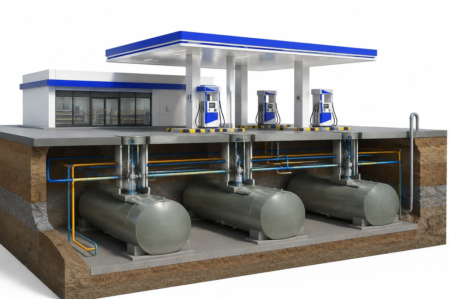
An underground fuel tank is the core storage component of a gas station fuel system. It works together with the submersible pump, underground piping, vapor recovery system, fuel level monitoring system and fuel dispenser.
For a reliable underground storage system, tank selection alone is not enough. Engineers and contractors should also consider tank structure, capacity, burial depth, backfill, leak detection, overfill protection, anti-floating measures and corrosion protection.
For projects in China, these requirements should be checked against applicable Chinese standards, including GB 50156-2021. International projects should additionally comply with the local fire, environmental, construction and petroleum-storage regulations applicable in the project country.
This guide focuses on the engineering parameters that are most useful when selecting and installing underground fuel tanks.
1. What Is an Underground Fuel Tank?
An underground fuel tank is a horizontal storage tank installed below ground to store gasoline, diesel and other petroleum products.
A typical underground fuel storage system consists of:
Underground Fuel Tank → Submersible Pump → Underground Piping → Fuel Dispenser → Fuel Nozzle
The tank is also connected to equipment such as:
- Tank manhole
- Fuel level monitoring system
- Leak detection system
- Vapor recovery piping
- Vent piping
- Overfill protection system
The tank, piping and monitoring equipment therefore need to be designed as one integrated system rather than as separate components.
2. How to Select Underground Fuel Tank Capacity
Tank capacity should be determined according to:
- Daily fuel consumption
- Fuel delivery frequency
- Number of fuel products
- Peak demand
- Available installation space
- Local regulations
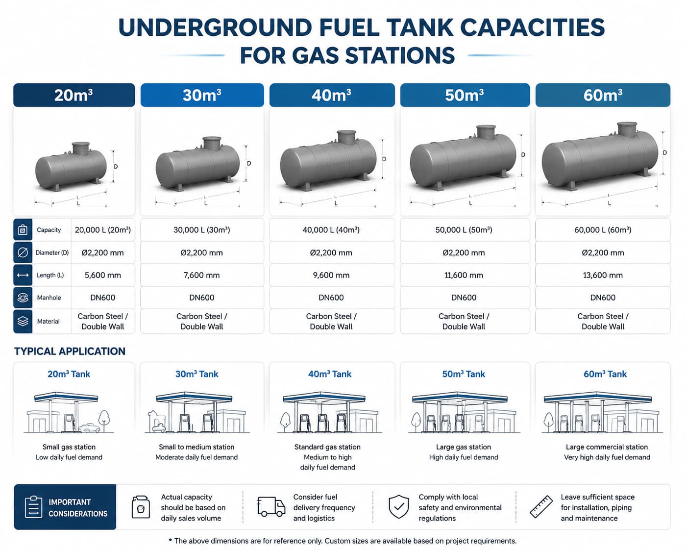
Common tank capacities include:
| Tank Capacity | Typical Application |
|---|---|
| 10–20 m³ | Small stations |
| 20–40 m³ | Standard stations |
| 40–60 m³ | Medium and large stations |
| 60 m³+ | Large commercial stations |
Typical commercial tank sizes include 20,000 L, 30,000 L, 40,000 L, 50,000 L and 60,000 L.
For example, a station could use:
| Fuel | Tank Configuration |
|---|---|
| Gasoline | 2 × 40 m³ |
| Diesel | 1 × 40 m³ |
| Total | 120 m³ |
The final capacity should be calculated from actual fuel demand rather than selected only according to a standard tank size.
3. Types of Underground Fuel Tanks
3.1 Single-Wall Steel Tanks
A single-wall tank uses one tank shell to contain the fuel.
Its main advantage is relatively simple construction, but there is no secondary containment layer. Therefore, leakage monitoring and corrosion protection are particularly important.
For projects where environmental protection requirements are stricter, double-wall tanks may provide a more comprehensive leakage-monitoring solution.
3.2 Double-Wall Underground Fuel Tanks
Common double-wall tank configurations include:
- Double-wall steel tanks
- Double-wall fiberglass-reinforced plastic (FRP) tanks
- Steel inner tank with an FRP outer layer
A double-wall tank consists of:
Inner Tank → Interstitial Space → Outer Layer
The interstitial space should be continuous and suitable for leakage monitoring.
| Tank Type | Inner Layer | Outer Layer | Main Characteristic |
|---|---|---|---|
| Double-wall steel | Steel | Steel | High mechanical strength |
| Double-wall FRP | FRP | FRP | High corrosion resistance |
| Steel-FRP | Steel | FRP | Strength + corrosion resistance |
The correct tank type depends on soil conditions, groundwater, traffic loads, environmental requirements and local regulations.
4. Underground Fuel Tank Structural Requirements
4.1 Steel Tank Plate Thickness
For steel tanks covered by the applicable Chinese technical requirements, minimum nominal steel plate thickness varies with tank diameter.
| Nominal Tank Diameter | Inner Tank / Single-Wall Shell | Inner Tank Head | Double-Wall Steel Outer Shell | Outer Shell Head |
|---|---|---|---|---|
| 800–1600 mm | 5 mm | 6 mm | 4 mm | 5 mm |
| 1601–2500 mm | 6 mm | 7 mm | 5 mm | 6 mm |
| 2501–3000 mm | 7 mm | 8 mm | 5 mm | 6 mm |
The design internal pressure of the steel tank should not be lower than 0.08 MPa under the cited requirement.
These values should be treated as project-specific design references, not as universal requirements for every country. The final tank design must comply with the applicable local standard and manufacturer’s certified design.
4.2 Double-Wall Interstitial Space
A double-wall tank should have a suitable interstitial space between the inner and outer walls.
The space serves two important functions:
- Provides secondary containment.
- Allows leakage between the two walls to be detected.
This is why simply specifying a “double-wall tank” is not enough. The tank must also have a properly designed leakage-monitoring system.
5. Underground Fuel Tank Burial Depth and Backfill
Tank burial depth is one of the most important installation parameters because the tank must withstand soil pressure, traffic loads and environmental conditions.
For the cited Chinese requirements:
| Installation Condition | Requirement |
|---|---|
| Non-traffic area | Tank top cover ≥ 0.5 m |
| Vehicle traffic area | Tank top ≥ 0.9 m below concrete pavement |
| Around steel tank | Neutral sand or fine soil ≥ 0.3 m |
Non-Traffic Areas
The cover above the tank should be at least 0.5 m.
Vehicle Traffic Areas
Where the tank is installed below a vehicle traffic area, the tank top should be at least 0.9 m below the concrete pavement under the cited requirement.
Backfill Around Steel Tanks
Steel tanks should be surrounded by suitable neutral sand or fine soil, with a thickness of at least 0.3 m under the cited requirement.
The backfill helps protect the tank from:
- Localized loads
- Mechanical damage
- Coating damage
- Unfavorable soil contact
For FRP tanks, backfill requirements should also follow the tank manufacturer’s installation instructions.
6. Underground Tank Anti-Floating Protection
An underground tank can experience significant upward buoyancy when the tank is empty and groundwater rises around it.
This risk is particularly important in areas with:
- High groundwater levels
- Heavy rainfall
- Flooding
- Poor drainage
If an underground tank moves, connected piping, electrical connections and tank fittings can be damaged.
Where buoyancy is possible, appropriate anti-floating measures may include:
- Concrete foundations
- Anchor straps
- Engineered anchoring systems
The anti-floating design should be based on actual groundwater conditions and the tank’s weight, dimensions and installation configuration.
7. Double-Wall Tank Leak Detection
Leak detection is one of the main advantages of a properly designed double-wall tank.
The interstitial space should allow leakage from either wall to be detected.
Leak Detection Riser
For the tank configurations covered by the cited requirements, a leak detection riser should generally have:
| Parameter | Reference Requirement |
|---|---|
| Riser diameter | Approximately 80 mm |
| Wall thickness | ≥ 4 mm |
| Location | Tank top longitudinal centerline |
| Bottom | Connected to interstitial space |
| Monitoring | Manual and/or online detection |
The monitoring arrangement should be designed so that leakage occurring at different points of the tank can be detected.
This is especially important for underground tanks because a leak may not be visible from the surface.
Planning a Double-Wall Fuel Tank System?
Need help matching the underground tank with leak detection, level monitoring, submersible pumps and underground piping?
Contact us to discuss your tank configuration and complete fuel storage system requirements.
8. Tank Manhole and Access Well
The tank manhole provides access to important underground equipment, including:
- Submersible pump
- Product piping connections
- Vapor recovery connections
- Level sensors
- Monitoring equipment
A manhole located under a vehicle traffic area should use a suitable traffic-rated sealed cover and frame.
The manhole should also provide sufficient working space for installation, inspection and maintenance.
9. Submersible Pump and Underground Piping
The underground tank normally works together with a submersible pump to deliver fuel to the dispenser.
The basic flow path is:
Fuel Tank → Submersible Pump → Underground Product Pipe → Fuel Dispenser → Nozzle
Pump selection should consider:
- Number of dispensers
- Required flow rate
- Pipeline length
- Pressure loss
- Vertical lifting requirements
- Number of fueling positions operating simultaneously
Typical pump specifications can vary significantly by project, so pump power and flow rate should not be selected independently from the dispenser and piping system.
A larger pump is not automatically a better solution. The pump should be matched to the complete hydraulic system.
10. Fuel Level, Leak Detection and Overfill Protection
Modern underground fuel tanks should integrate fuel level monitoring and appropriate leakage detection.
10.1 Fuel Level Monitoring
A tank monitoring system can provide information such as:
- Current fuel level
- Fuel volume
- Fuel consumption
- High-level alarm
- Abnormal fuel changes
- Water detection, where applicable
For stations equipped with vapor recovery systems, the cited Chinese requirements specify a fuel tank liquid-level monitoring system with a high-level alarm function.
For single-wall tanks, the cited requirement also includes leakage detection, with a recommended detection resolution of no more than:
0.8 L/h
This parameter is important when evaluating the sensitivity of a tank monitoring system.
11. Overfill Protection During Fuel Unloading
Overfill protection is required during tanker unloading to prevent fuel from exceeding the safe filling level.
Under the cited requirements:
| Tank Fill Level | Protection Action |
|---|---|
| 90% | High-level alarm |
| 95% | Automatic stop of fuel filling |
Example: 50,000-L Tank
At 90%:
50,000 × 90% = 45,000 L
At 95%:
50,000 × 95% = 47,500 L
Therefore:
- 45,000 L → High-level alarm
- 47,500 L → Automatic filling stop
The alarm should be installed or displayed at a location where operating personnel can easily notice it.
12. Static Electricity Protection for Non-Metallic Fuel Tanks
For non-metallic layers such as FRP that are in direct contact with fuel, the surface resistivity should be less than 10⁹ Ω.
If this requirement cannot be met, conductive metal objects such as immersed steel plates, steel inlet risers or outlet pipes should be installed to dissipate static electricity.
The total surface area of immersed metal objects should meet:
A = 0.04Vₜ
Where:
- A = total surface area of immersed metal objects (m²)
- Vₜ = tank capacity (m³)
For example, a 50 m³ tank requires at least 2.0 m² of immersed metal surface area.
The metal components used for static dissipation should also be properly grounded according to the applicable grounding requirements.
13. Underground Steel Tank Corrosion Protection
Steel tanks installed underground are exposed to:
- Soil moisture
- Groundwater
- Corrosive soil
- Electrochemical corrosion
Therefore, the external surface of a steel tank in contact with soil requires an appropriate corrosion protection system.
Possible protection measures include:
- Protective coatings
- Corrosion-resistant tank materials
- Cathodic protection where required
- Proper backfill
- Appropriate installation procedures
For projects applying the cited Chinese requirements, the external corrosion protection of steel tanks should meet the applicable technical standard and should not be lower than the specified enhanced protection grade.
A double-wall structure does not eliminate the need for appropriate corrosion protection of steel components.
14. Complete Underground Fuel Storage System
A complete underground fuel storage system normally includes:
| Component | Main Function |
|---|---|
| Underground Fuel Tank | Stores fuel |
| Tank Manhole | Provides equipment access |
| Submersible Pump | Transfers fuel |
| Product Piping | Delivers fuel |
| Vapor Recovery Piping | Handles fuel vapor |
| Vent Piping | Manages tank pressure |
| Level Monitoring System | Measures fuel quantity |
| Leak Detection System | Detects leakage |
| Overfill Protection | Prevents excessive filling |
| Emergency Shutdown System | Stops fuel supply when required |
The tank should therefore be designed together with the pump, piping, monitoring and safety systems rather than treated as an isolated product.
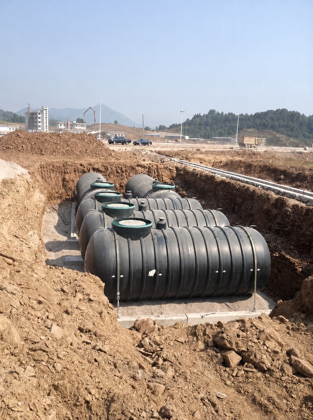
15. Common Underground Fuel Tank Installation Problems
Problem 1: Incorrect Tank Capacity
Risk: Insufficient storage or excessive delivery frequency.
Solution: Calculate capacity from actual fuel demand, delivery frequency and fuel mix.
Problem 2: Incorrect Burial Depth
Risk: Insufficient protection against soil or traffic loads.
Solution: Check the required cover before excavation and tank placement.
Problem 3: No Anti-Floating Design
Risk: Tank movement during groundwater rise or flooding.
Solution: Evaluate groundwater conditions and install anchoring where necessary.
Problem 4: Inadequate Leak Detection
Risk: Underground leakage may remain undetected.
Solution: Provide appropriate interstitial or tank monitoring according to tank type.
Problem 5: Incorrect Overfill Protection
Risk: Fuel overflow during tanker unloading.
Solution: Verify the 90% alarm and 95% automatic shutoff functions before commissioning.
16. Underground Fuel Tank Installation Checklist
Before installation and commissioning, verify:
☐ Tank capacity and fuel type
☐ Single-wall or double-wall structure
☐ Tank material: steel / FRP / composite
☐ Tank structural design and plate thickness
☐ Interstitial monitoring space
☐ Leak detection riser
☐ Burial depth
☐ Backfill material and thickness
☐ Anti-floating protection
☐ Tank manhole and access well
☐ Submersible pump selection
☐ Product piping
☐ Vapor recovery connection
☐ Level monitoring system
☐ Leak detection system
☐ 90% high-level alarm
☐ 95% automatic filling shutoff
☐ Electrostatic protection where applicable
☐ External corrosion protection
☐ Emergency shutdown system
Conclusion
A reliable underground fuel tank system is more than a buried storage vessel. Its safety and performance depend on the correct combination of tank structure, burial depth, backfill, leak detection, overfill protection, anti-floating measures, corrosion protection and fuel delivery equipment.
For engineering reference, several key values should be checked during project design:
- 0.5 m minimum cover in non-traffic areas
- 0.9 m tank-top depth below concrete pavement in traffic areas
- 0.3 m minimum surrounding backfill for steel tanks
- 80 mm approximate leak detection riser diameter
- 4 mm minimum reference riser wall thickness
- 0.08 MPa minimum design internal pressure for steel tanks under the cited requirement
- 90% high-level alarm point
- 95% automatic filling shutoff point
- 0.8 L/h leakage detection resolution for applicable single-wall tank monitoring
- 10⁹ Ω surface resistivity limit for applicable non-metallic fuel-contact surfaces
These values provide a practical starting point for engineering review, but the final design should always be checked against the regulations and certified requirements applicable in the project country.
For gas station owners, contractors and equipment distributors, the most reliable approach is to coordinate the underground tank, submersible pump, piping, vapor recovery, monitoring and dispensing systems as one integrated fuel storage and delivery solution.
Need a Complete Underground Fuel Storage Solution?
From underground fuel tanks and submersible pumps to piping, monitoring and fuel dispensers, we can help coordinate the equipment required for your gas station project.
Contact us today with your project requirements and let us help you build a suitable fuel storage and dispensing system.