
Fuel Tank Level Monitoring System: Installation, Wiring, Maintenance & Troubleshooting Guide
News 2026年 8月 7日 95
Introduction
In modern gas stations and petroleum storage facilities, accurate fuel inventory management and real-time tank monitoring are essential for safe operation, efficient management, and reducing potential risks.
A professional fuel tank level monitoring system provides real-time information about underground storage tanks, including:
- Fuel level monitoring
- Water level detection
- Fuel temperature monitoring
- Inventory management
- Leakage alarm monitoring
- Historical data recording
By integrating intelligent controllers, magnetostrictive level sensors, safety barrier modules, and communication systems, the tank monitoring system helps fuel station operators improve operational efficiency while meeting safety and explosion-proof requirements.
For new gas station construction projects, station upgrades, or petroleum storage system installation, correct installation and commissioning are critical to ensuring long-term reliability.
A complete fuel station solution normally includes fuel dispensers, underground storage tanks, submersible pumps, tank monitoring systems, and related safety equipment.
1. Overview of Fuel Tank Level Monitoring System
A fuel tank level monitoring system is an intelligent management system designed to monitor underground storage tanks in gas stations and petroleum facilities.
The system mainly consists of:
- Intelligent monitoring controller
- Magnetostrictive level gauge
- Safety barrier module
- Power supply module
- Communication interface
The system continuously collects tank operation information and displays important parameters in real time, including:
- Fuel volume
- Water level
- Temperature
- Leakage status
- Alarm information
- Historical operation records
The controller works as the central processing unit of the complete monitoring system. It is responsible for:
- Data processing
- Display operation
- Communication management
- Sensor power supply
- Alarm management
For modern gas stations, a reliable tank monitoring system helps improve fuel inventory accuracy and reduce risks caused by manual inspection errors.
Main Functions of Fuel Tank Monitoring System
Real-Time Fuel Level Monitoring
The system continuously monitors the liquid level inside underground fuel tanks and provides accurate fuel inventory information.
This allows operators to understand remaining fuel quantity and improve fuel management efficiency.
Water Level Detection
Water accumulation inside underground storage tanks may affect fuel quality and equipment operation.
The monitoring system detects water levels at the bottom of storage tanks and provides early warnings when abnormal conditions occur.
Temperature Monitoring
Fuel temperature data can be collected and recorded for better inventory management and operational analysis.
Leakage Detection
The system supports leakage monitoring sensors to detect abnormal conditions around fuel storage tanks and provide early warning signals.
Data Recording and Reporting
The system can automatically store:
- Historical operating data
- Alarm records
- Tank status information
These records help operators analyze system performance and improve station management.
2. System Structure and Main Components
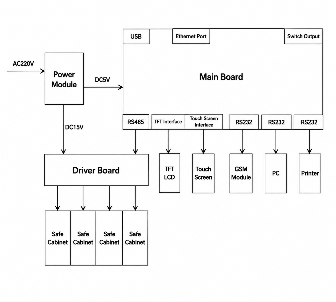
The controller is not only the user operation and display interface but also the data processing and storage center of the complete fuel tank monitoring system.
The main components include:
TFT Color Touch Screen
The system uses:
8-inch 800 × 600 TFT color touchscreen
The display provides:
- Real-time monitoring information
- Tank status
- Alarm messages
- System configuration
- Operation interface
Operators can easily check fuel inventory, alarm conditions, and system operation status through the touchscreen.
Main Processing Board
The main control board uses an embedded processor and peripheral circuits to process:
- Sensor signals
- Communication data
- Alarm information
- Historical records
It works as the control center of the complete tank measurement system.
Safety Barrier Module
The safety barrier is an important explosion-proof protection component.
Its main functions include:
- Providing safe electrical isolation
- Protecting intrinsically safe circuits
- Preventing hazardous energy transmission
- Ensuring reliable connection between monitoring equipment and sensors
The safety barrier is especially important because fuel stations contain potentially explosive environments.
Power Supply Module
The power module provides stable and reliable power for the complete system.
3. Safety Requirements Before Installation
Because fuel tank monitoring systems are mainly installed in:
- Gas stations
- Petroleum storage facilities
- Fuel terminals
installation must strictly follow safety and explosion-proof requirements.
Before installation, technicians should confirm that all equipment, wiring, and safety components meet applicable standards.
Important Safety Rules
3.1 Do Not Power On Before Installation Is Completed
The system must remain powered off until all installation work is finished.
Incorrect installation may cause:
- Electric shock
- Equipment damage
- Explosion risks
Power should only be supplied after:
- Wiring inspection is completed
- Grounding is confirmed
- Safety checks are finished
3.2 Installation Personnel Requirements
Installers must:
- Understand explosion-proof electrical requirements
- Follow installation instructions carefully
- Confirm all safety devices are correctly installed
Only qualified personnel should perform electrical installation work.
3.3 Equipment Installation Location
The following equipment must be installed in a safe area:
- Controller
- Printer
- Management terminal equipment
Recommended installation locations:
- Control room
- Office
- Non-hazardous electrical room
The controller must not be installed directly in hazardous areas containing explosive gas mixtures.
3.4 Explosion-Proof Components Cannot Be Modified
Products that have passed explosion-proof certification must not be:
- Internally modified
- Replaced with unauthorized components
- Disassembled without approval
Any modification may affect explosion-proof performance and system safety.
4. Controller Installation Guide
The controller is the central control unit of the fuel tank level monitoring system.
Correct installation ensures:
- Stable operation
- Accurate measurement
- Reliable communication
- Long service life
Before installation, technicians should check the installation environment and confirm that all electrical requirements meet safety standards.
Installation Location Requirements
The controller must be installed in a safe area, such as:
- Control room
- Office
- Electrical equipment room
The controller must not be installed directly in hazardous areas.
Recommended installation conditions:
- Dry environment
- Good ventilation
- Easy maintenance access
- Avoid direct sunlight
- Avoid water exposure
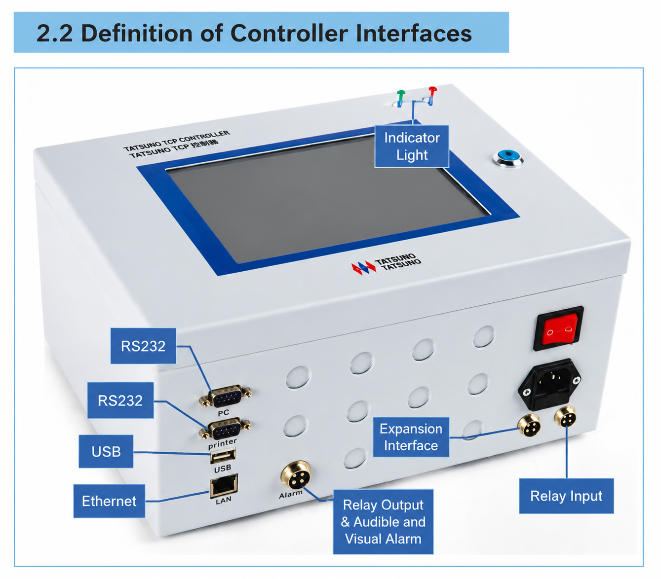
Controller Installation Steps
Follow these installation procedures:
Step 1: Select Installation Position
Choose a suitable wall or desktop location where operators can easily:
- Observe the display
- Operate the system
- Perform maintenance
Step 2: Fix the Installation Bracket
According to the installation dimensions:
- Mark mounting holes on the wall.
- Drill holes according to the marked positions.
- Install expansion bolts.
- Secure the controller mounting plate firmly.
The installation should ensure:
- Stable fixation
- Good appearance
- Convenient operation
Step 3: Install the Controller
Securely mount the controller onto the mounting plate.
Check that:
- The equipment is stable.
- All fixing points are tightened.
- The display angle is suitable for operation.
Step 4: Ground Connection
The controller grounding terminal must be reliably connected to earth.
Required grounding wire:
6 mm² multi-core flexible copper wire
The grounding connection must be:
- Firm
- Reliable
- Properly connected to the station grounding system
A correct grounding system is important for:
- Electrical safety
- Explosion-proof protection
- Stable communication
Step 5: Power Supply Connection
The controller uses:
AC220V power supply
When connecting power:
- Confirm correct polarity.
- Ensure wiring is secure.
- Do not energize the system before all installation work is completed.
5.Electrical Wiring Requirements
Correct wiring is one of the most important steps during installation.
Improper wiring may cause:
- Communication failure
- Incorrect measurement
- Equipment damage
- Safety risks
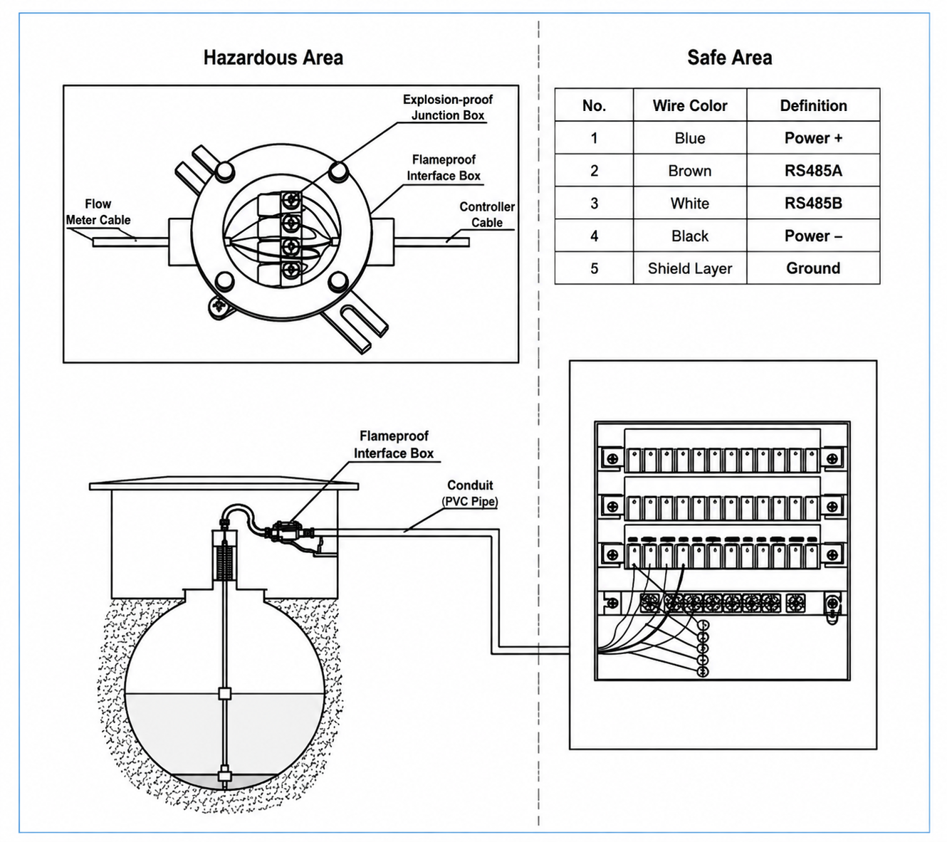
Safety Barrier Wiring Requirements
The cables from the tank level sensor must be correctly connected to the corresponding safety barrier terminals inside the controller.
The cable shielding layer must be connected to:
Safety barrier grounding terminal
The safety barrier must be reliably connected to:
The fuel station grounding system
Important Safety Requirements:
Before completing wiring:
Do not supply power to the entire system.
The system can only be powered after:
- All cables are connected correctly.
- Grounding is confirmed.
- Installation inspection is completed.
Separation Between Intrinsically Safe and Non-Intrinsically Safe Terminals
To maintain explosion-proof performance:
The distance between:
- Intrinsically safe terminals
- Non-intrinsically safe terminals
must be:
Not less than 50 mm
This separation helps prevent electrical interference and improves system safety.
6. Leak Detection Sensor Installation Guide
Leak detection sensors are important components used in underground fuel tank monitoring systems.
They help operators identify abnormal conditions and prevent potential fuel leakage risks.
Different sensor types require different safety barriers.
Two-Wire Leak Detection Sensor
For two-wire sensors:
Required safety barrier:
GSB05 Safety Barrier
Connection:
- Sensor wire 1 → Signal X terminal
- Sensor wire 2 → GND terminal
The sensor number corresponds to the configured sensor number in the leakage detection settings.
Maximum connection:
One safety barrier can connect up to 8 leak detection sensors
Three-Wire Leak Detection Sensor
For three-wire sensors:
Required safety barrier:
GSB04 Safety Barrier
Connection terminals:
- Power +
- Signal X
- Power –
The sensor number corresponds to the leakage monitoring configuration.
Maximum connection:
One safety barrier can connect up to 4 leak detection sensors
Four-Wire Leak Detection Sensor
For four-wire sensors:
Required safety barrier:
GSB03 Safety Barrier
Connection:
- Power +
- RS485 A
- RS485 B
- Power –
The communication address must match the sensor number configured in the system.
Maximum connection:
One safety barrier can connect up to 3 leak detection sensors
7.Connection With Fuel Station Management System
The tank monitoring controller can communicate with the station management platform.
When connecting the controller with the management system:
Use the supplied:
RS232 communication cable
Connection steps:
- Connect the RS232 cable to the controller communication port.
- Connect the other end to the management computer.
- Configure communication parameters.
- Confirm successful data transmission.
The system can provide:
- Tank inventory data
- Alarm information
- Historical records
- Operating status
for centralized station management.
8. Installation Inspection Before Power-On
Before starting the system, carefully check the following items.
Electrical Inspection
Confirm:
✓ Power wiring is correct
✓ Ground connection is reliable
✓ Safety barrier wiring is correct
✓ Sensor cables are properly connected
Mechanical Inspection
Confirm:
✓ Controller installation is stable
✓ All components are correctly installed
✓ No damaged cables or terminals exist
System Inspection
Confirm:
✓ Communication works normally
✓ Sensors are recognized
✓ Display operates correctly
Only after completing all checks:
The complete system can be powered on.
9. Explosion-Proof Requirements and Safety Standards
Fuel tank level monitoring systems are widely used in:
- Gas stations
- Petroleum storage facilities
- Fuel terminals
- Underground tank monitoring applications
Because these environments may contain flammable gases and vapors, installation and operation must strictly comply with explosion-proof safety requirements.
The system has been tested according to:
GB3836.1 — Equipment for Explosive Gas Atmospheres: General Requirements
and
GB3836.4 — Equipment Protection by Intrinsically Safe Circuit “i”
These standards ensure that the monitoring equipment can safely operate together with intrinsically safe devices installed in hazardous areas.
Application in Hazardous Areas
The system can be used together with intrinsically safe equipment installed in:
- Zone 0
- Zone 1
- Zone 2
hazardous areas.
The controller and printer equipment themselves must be installed in:
Safe areas
such as:
- Control rooms
- Offices
- Non-hazardous electrical rooms
The connection between safe-area equipment and hazardous-area sensors must be completed through certified safety barriers.
Explosion-Proof Installation Requirements
Do Not Modify Explosion-Proof Components
Products that have passed explosion-proof certification must not be:
- Disassembled without authorization
- Modified internally
- Replaced with non-certified components
Unauthorized modification may reduce explosion-proof performance.
Confirm Grounding Reliability
The safety barrier grounding terminal must be connected using:
6 mm² multi-core copper wire
to the fuel station grounding system.
Reliable grounding helps ensure:
- Electrical safety
- Signal stability
- Explosion-proof protection
Complete Installation Before Power Supply
Before powering the system, confirm:
- All wiring is completed.
- Sensor connections are correct.
- Grounding is reliable.
- Communication cables are properly installed.
Only after inspection is completed can the system be energized.
10. Common Problems and Troubleshooting Guide
During long-term operation, fuel station operators may encounter communication problems, display failures, or sensor abnormalities.
A proper troubleshooting process helps operators quickly identify problems and restore normal operation of the fuel tank level monitoring system.
Problem 1: Communication Failure Between Controller and Level Gauge
Possible Causes
1. Communication Cable Failure
The sensor communication cable may be:
- Broken
- Loose
- Incorrectly connected
2. Incorrect Wiring Sequence
The communication wires may not match the required terminal positions.
3. Configuration Loss
System parameters may be lost after maintenance or equipment replacement.
4. Safety Barrier Failure
A damaged safety barrier may affect communication transmission between the sensor and controller.
5. Level Gauge Malfunction
The tank level sensor itself may have a fault.
Solutions
Check the system step by step:
- Inspect communication cables.
- Confirm correct wiring sequence.
- Reconfigure tank parameters.
- Replace damaged safety barrier if necessary.
- Test or replace the level sensor.
Problem 2: Incorrect System Time or Clock Error
Possible Causes
- Incorrect time setting
- Internal battery power is low
Solutions
- Reset system time using the correct format.
- Replace the internal battery if voltage is insufficient.
Problem 3: Display Screen Is Black or No Display
Possible Causes
Situation 1:
The system may be operating in normal screen-saving mode.
Situation 2:
Backlight failure.
Situation 3:
Touch screen or display module problem.
Solutions
- Touch the screen to wake up the display.
- Restart the controller.
- Replace the LCD display module if necessary.
- Replace the touch screen if operation function fails.
Problem 4: Cannot Connect to Station Management Software
Possible Causes
1. Computer Serial Port Occupied
Another program may be using the communication port.
2. Incorrect Software Configuration
Communication parameters may not match the monitoring controller.
3. RS232 Communication Cable Failure
The cable connection may be unstable.
Solutions
- Restart the management computer.
- Check communication parameters.
- Confirm equipment type configuration.
- Check RS232 cable connection.
Problem 5: Controller Has No Display and No Response
Possible Causes
- Power supply failure
- Fuse damage
- DC power module failure
Solutions
- Check AC power input.
- Replace damaged fuse.
- Replace DC power supply module.
Looking for reliable fuel station equipment and technical support?
Our team can help with equipment selection, installation guidance and after-sales service.
11. Daily Maintenance Recommendations for Fuel Tank Monitoring Systems
Regular maintenance helps extend equipment service life and reduces unexpected downtime.
For gas station operators, routine inspection is important to ensure accurate fuel inventory monitoring and reliable safety protection.
Check Electrical Connections Regularly
Inspect:
- Terminal screws
- Grounding connections
- Sensor cables
- Communication cables
Ensure all connections remain:
- Tight
- Clean
- Corrosion-free
Check Safety Barrier Operation
Regularly confirm:
- Safety barrier status
- Ground connection
- Signal communication
A damaged safety barrier may cause communication interruption or abnormal sensor operation.
Review Alarm Records
Operators should regularly check:
- Leakage alarms
- Abnormal fuel level changes
- Communication alarms
- System warnings
Early detection helps prevent larger operational problems.
Maintain Clean Equipment Environment
Keep the controller installation area:
- Dry
- Dust-free
- Protected from water
Avoid placing unnecessary objects around the equipment.
Perform Regular System Testing
Recommended checks:
- Sensor communication test
- Display function test
- Data transmission test
- Alarm function test
Regular testing ensures the complete tank monitoring system remains reliable.
12. Complete Fuel Station Solution From Professional Equipment Suppliers
A reliable gas station requires more than a single piece of equipment.
Professional suppliers should provide complete solutions including:
- Fuel dispensers
- Submersible pumps
- Underground tank equipment
- Fuel tank level monitoring systems
- Leak detection systems
- Installation guidance
- Technical support
- Maintenance services
By integrating equipment supply, technical support, and project experience, fuel station operators can build safer, more efficient, and more reliable petroleum service systems.
Summary
Level monitoring systems are crucial equipment in modern gas stations for ensuring the safe operation of oil tanks. Through the coordination of level gauges, controllers, sensors, and safety barriers, they achieve real-time monitoring of oil levels, water levels, temperature, and leakage conditions. Proper installation, standardized wiring, and regular maintenance are key to ensuring stable system operation and improving gas station safety and management efficiency.