
Fuel Dispenser Installation and Layout Requirements for Gas Stations
News 2026年 8月 25日 121
A fuel dispenser is one of the most visible pieces of equipment at a gas station, but its installation is closely connected with the underground fuel system, electrical system, vapor recovery system and overall station layout.
A properly selected and installed fuel dispenser should not only meet the required fuel flow and nozzle configuration, but also work reliably with the underground storage tank, submersible pump, fuel piping and safety systems.
This guide explains the key points to consider when planning fuel dispenser installation and layout for a gas station project.
1. Where Should a Fuel Dispenser Be Installed?
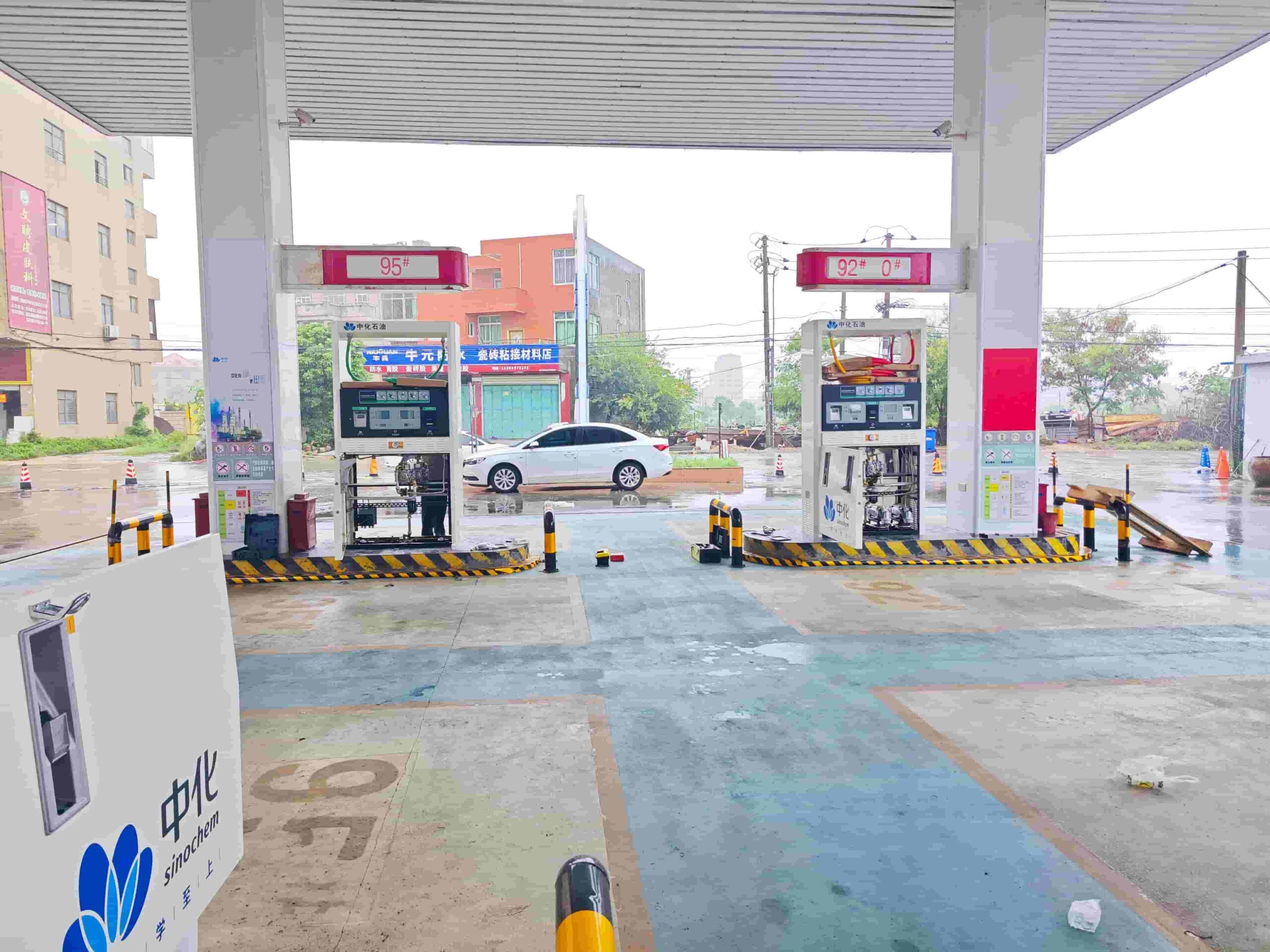
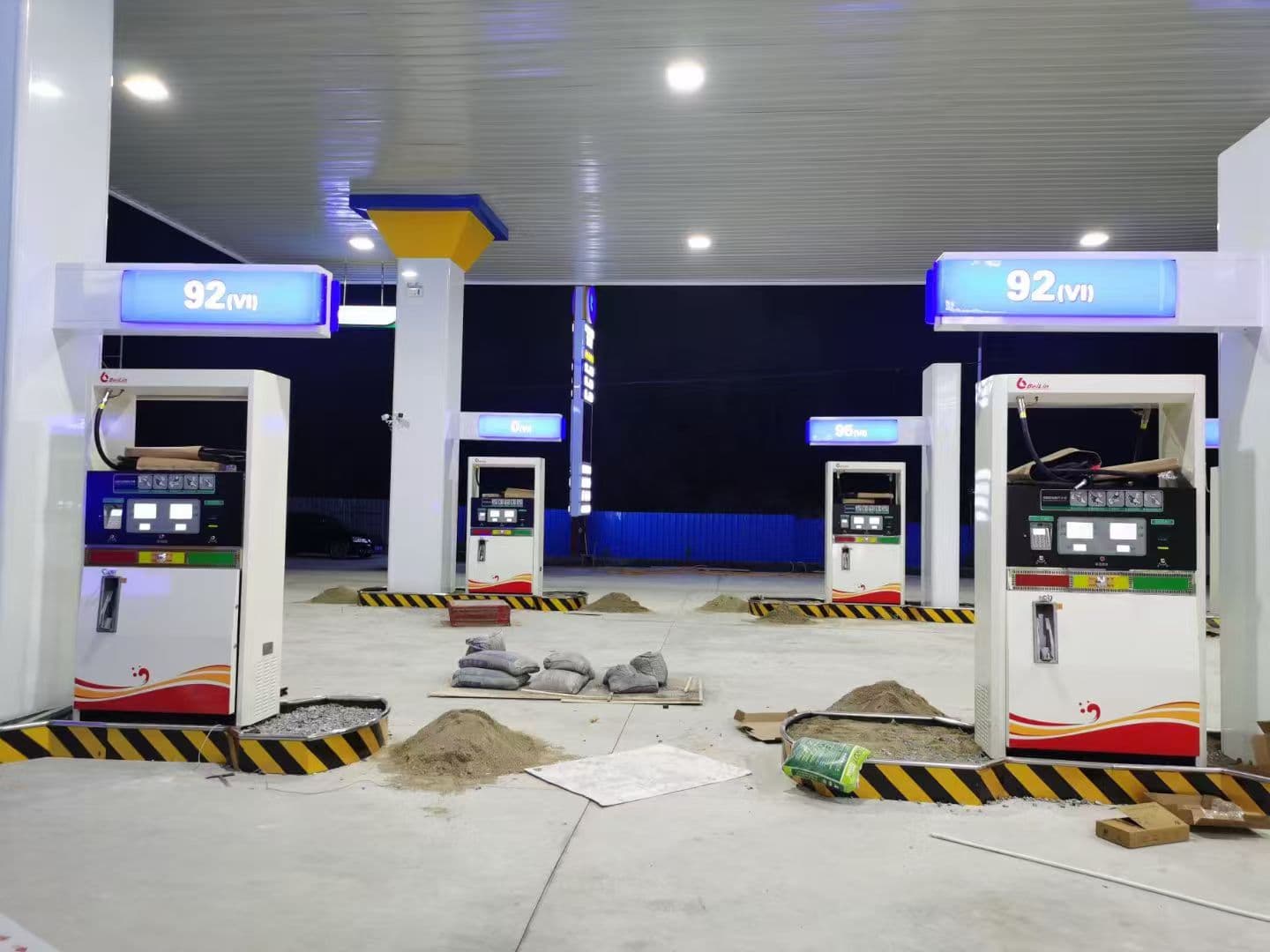
Fuel dispensers are normally installed on dedicated fueling islands beneath the station canopy.
The dispenser location should be planned together with:
- Vehicle entry and exit routes
- Fueling positions
- Underground fuel piping
- Dispenser sumps
- Electrical conduits
- Vapor recovery piping
- Emergency shut-off systems
- Traffic and pedestrian movement
The dispenser should not be treated as an isolated piece of equipment. Its location affects the routing of underground piping and the operation of the entire fuel dispensing system.
Under GB 50156-2021, fuel dispensers shall not be installed indoors.
For a new gas station project, the dispenser layout should therefore be considered during the overall site and process design stage rather than after the underground piping has already been installed.
2. Fuel Dispenser Foundation and Installation
A fuel dispenser normally needs a stable concrete foundation or fueling island structure.
The installation should provide sufficient support for the dispenser and maintain proper alignment with the underground piping.
Typical installation considerations include:
- Concrete foundation and anchor points
- Correct dispenser positioning
- Vertical alignment
- Underground pipe entry
- Dispenser sump arrangement
- Electrical cable routing
- Vapor recovery connections
- Protection against vehicle impact
The bottom of the dispenser is particularly important because it connects the above-ground dispensing equipment with the underground fuel system.
For projects using a dispenser sump, the sump provides an accessible area for pipe connections, valves and inspection while helping contain potential leakage.
3. Connection Between the Fuel Dispenser and Underground Piping
The fuel dispenser is normally connected to the underground fuel system through the dispenser base or dispenser sump.
A typical fuel delivery route can be represented as:
Underground Storage Tank → Submersible Pump → Underground Fuel Pipe → Dispenser Sump → Fuel Dispenser
For a station using a submersible pump system, one pump can be designed to supply multiple dispensers depending on the system configuration and project requirements.
GB 50156-2021 states that gas stations are recommended to use a submersible-pump arrangement capable of supplying multiple dispensers or nozzles. When self-priming dispensers are used, each dispenser should have separate product-specific inlet piping and a tank bottom valve.
This is one reason why fuel dispenser selection should be coordinated with the underground piping and pump system.
4. Safety Shut-Off at the Fuel Dispenser
Safety protection is an important part of dispenser installation.
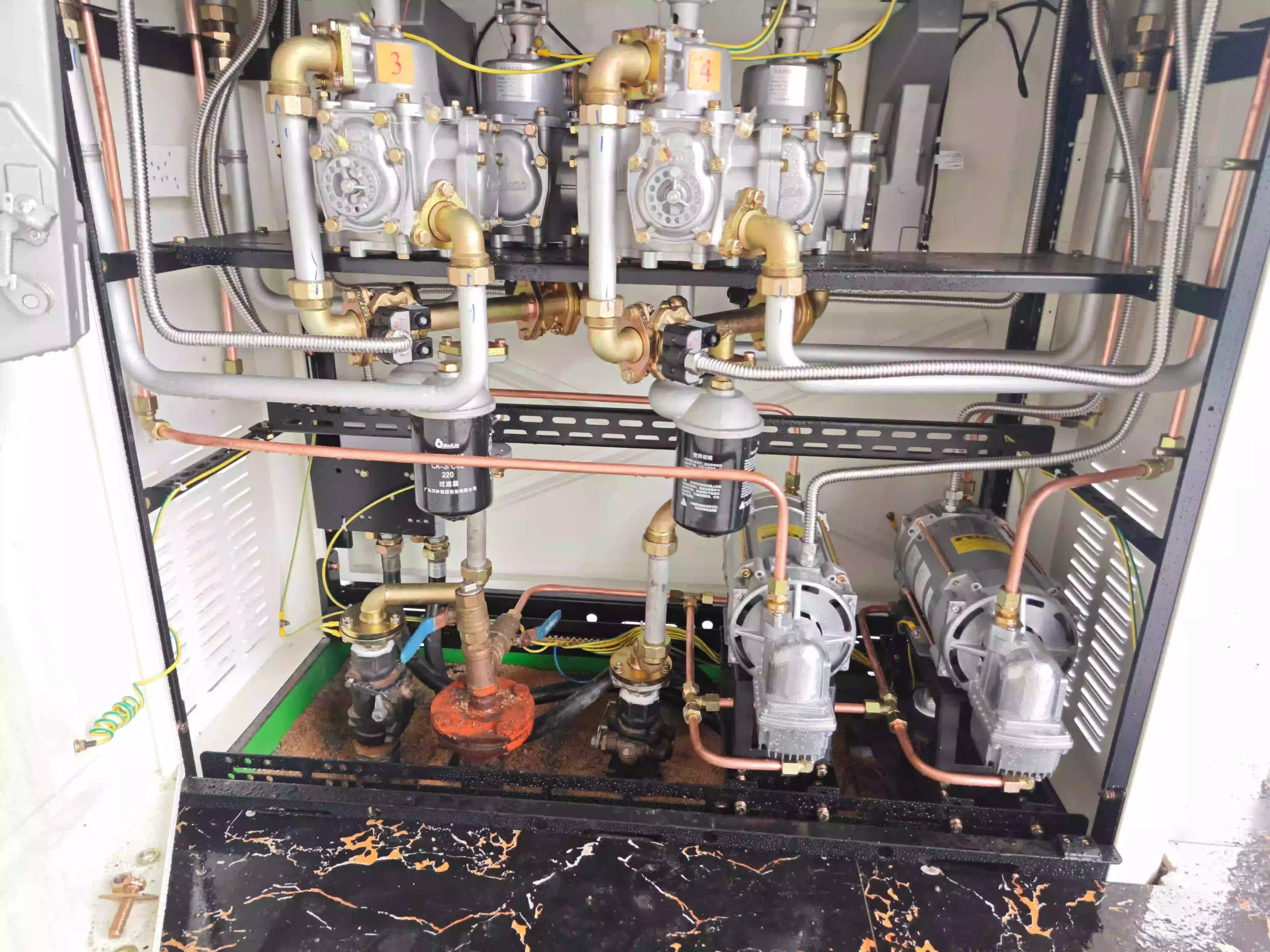
For a dispenser supplied by a submersible pump under positive pressure, GB 50156-2021 requires a shear valve to be installed in the supply piping at the bottom of the dispenser.
The shear valve is designed to automatically close when the dispenser is impacted or exposed to fire conditions.
This arrangement helps isolate the fuel supply and reduce the potential release of fuel during an emergency.
The dispenser installation should therefore consider the relationship between:
Dispenser → Shear Valve → Underground Fuel Pipe → Submersible Pump
The valve location must also remain accessible for inspection and maintenance.
5. Fuel Nozzle Configuration
The number of nozzles is one of the most important factors when selecting a fuel dispenser.
Common configurations include:
- 2-nozzle dispensers
- 4-nozzle dispensers
- 6-nozzle dispensers
- 8-nozzle dispensers
The correct configuration depends on the number of fuel products, number of fueling positions and expected customer demand.
For example, a station selling gasoline and diesel may require a different dispenser configuration from a larger station offering multiple gasoline grades and diesel.
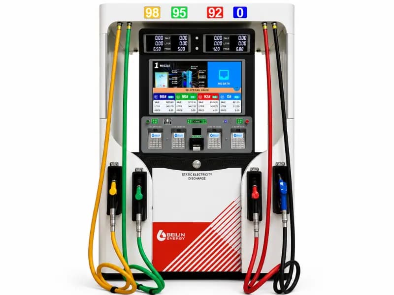
When a single dispenser serves multiple fuel products, the dispenser should have clear fuel identification. GB 50156-2021 requires text identification for the fuel products at the nozzle positions and color identification for the nozzles.
For gasoline dispensers, the standard also specifies that self-closing nozzles should be used and that gasoline nozzle flow should not exceed 50 L/min.
6. Six-Nozzle vs. Eight-Nozzle Fuel Dispensers
The choice between six-nozzle and eight-nozzle equipment should be based on the station’s actual operating requirements.
Six-Nozzle Fuel Dispenser
A six-nozzle configuration may be suitable for:
- Small and medium-sized stations
- Stations with fewer fuel products
- Projects where the fueling island has limited space
- Standard gasoline and diesel configurations
Eight-Nozzle Fuel Dispenser
An eight-nozzle configuration can be useful for:
- Larger fueling stations
- Multiple gasoline grades
- Higher fueling demand
- More flexible product allocation
- Projects requiring more fueling positions
However, more nozzles do not automatically mean better performance.
The final configuration should be determined by the station layout, fuel products, expected traffic, piping design and required flow rate.
Not sure whether you need a 6-nozzle or 8-nozzle dispenser? Send us your station layout and fuel product requirements.
7. Fuel Dispenser and Vapor Recovery System
For gasoline stations, the fuel dispenser may also form part of the vapor recovery system.
GB 50156-2021 requires gas stations to use a gasoline fueling vapor recovery system. The standard specifies a vacuum-assisted system, with vapor recovery piping between gasoline dispensers and the underground storage tanks. Multiple gasoline dispensers may share a common vapor recovery header, whose nominal diameter should not be less than 50 mm.
The standard also specifies that the vapor recovery system should prevent vapor from flowing back toward the nozzle.
Therefore, when installing a gasoline dispenser, the project should coordinate:
Fuel Pipe + Vapor Recovery Pipe + Electrical Connection + Dispenser
rather than treating each system independently.
8. Fuel Dispenser Installation and Electrical Requirements
The dispenser is located in an area where flammable fuel and vapor may be present, so electrical installation is an important part of the overall design.
Depending on the project and applicable local regulations, the installation may involve:
- Explosion-protected electrical equipment
- Proper cable routing
- Grounding and bonding
- Emergency shut-off wiring
- Control system connections
- Vapor recovery control wiring
- Equipment grounding
The exact electrical classification and equipment requirements should be determined according to the applicable national and local regulations for the project location.
For export projects, this is particularly important because electrical standards may differ between countries.
9. How to Select the Right Fuel Dispenser for a Gas Station Project
Before purchasing a fuel dispenser, the project owner or contractor should confirm several technical parameters.
Key information to provide to the supplier
1. Number of fuel products
For example:
- Gasoline
- Diesel
- Multiple gasoline grades
2. Number of nozzles
For example:
- 4 nozzles
- 6 nozzles
- 8 nozzles
3. Required flow rate
The required flow rate should be matched with the expected fueling demand and the complete fuel delivery system.
4. Pumping system
Determine whether the station uses:
- Submersible turbine pumps
- Self-priming dispensers
5. Power supply
Confirm the local electrical supply, such as:
- 220 V
- 380 V
- Single-phase
- Three-phase
6. Vapor recovery
Determine whether gasoline vapor recovery is required and how the dispenser will connect to the vapor recovery piping.
7. Local standards
For international projects, the dispenser should be configured according to the electrical, safety, metering and certification requirements of the destination country.
10. Choosing a Fuel Dispenser for Your Project
There is no single fuel dispenser configuration that is suitable for every gas station.
A small station may require a compact dispenser with fewer nozzles, while a high-throughput station may require an eight-nozzle configuration and a more complex underground fuel distribution system.
For example, an eight-nozzle dispenser can provide more flexible fuel product allocation when the station needs multiple fueling options.
Our fuel dispenser range includes different configurations for different station layouts and project requirements.
Explore our fuel dispenser products:
When selecting a dispenser, we recommend confirming the number of fuel products, nozzles, required flow rate, power supply, pump type and vapor recovery requirements before placing an order.
11. What Information Should You Send When Requesting a Fuel Dispenser Quote?
If you are planning a new gas station or replacing existing dispensers, providing the right information can significantly speed up the quotation process.
You can send us:
- Number of dispensers
- Number of nozzles per dispenser
- Fuel products
- Required flow rate
- Pump type
- Power supply
- Vapor recovery requirements
- Quantity required
- Destination country
- Project drawings, if available
Our team can then help evaluate the dispenser configuration and coordinate it with the underground fuel system.
Need a Fuel Dispenser for Your Gas Station Project?
Send us your project requirements and we can help you select a suitable fuel dispenser configuration.
Important Note
The technical requirements in this article are based in part on GB 50156-2021 and are intended as general engineering information. Gas station projects must also comply with the applicable codes, regulations, certification requirements and authority approvals in the project location.