
Fuel Tank Level Monitoring System: Installation, Working Principle & Troubleshooting Guide
News 2026年 8月 10日 89
A reliable fuel tank level monitoring system is one of the most important safety and management systems in modern gas stations. Accurate measurement of fuel level, water level, and temperature inside underground storage tanks helps operators improve inventory management, prevent fuel losses, detect abnormal conditions, and ensure safe operation.
A magnetostrictive tank level gauge is widely used in fuel stations because of its high accuracy, excellent stability, and low maintenance requirements. Unlike traditional mechanical measuring devices, it has almost no moving mechanical parts and can provide long-term reliable monitoring in harsh underground environments.
- Working Principle of Magnetostrictive Tank Level Gauge
A magnetostrictive level gauge uses advanced sensing technology based on the Wiedemann effect and Villari effect to accurately measure liquid levels.
The system mainly consists of:
- Electronic module
- Magnetostrictive waveguide wire
- Protective tube
- Magnetic float
- Temperature sensor
During operation, the float moves according to the fuel level inside the underground tank. The magnetic field generated by the float interacts with the magnetostrictive wire, creating a torsional wave signal.
The electronic module calculates the travel time of this signal and converts it into accurate liquid level information.
The system can measure:
- Fuel level
- Water level
- Fuel temperature
- Average temperature inside the tank
The collected data is processed through filtering algorithms and transmitted to the controller through digital communication.
Because the system has almost no mechanical moving parts, it provides:
- High measurement accuracy
- Long service life
- Simple installation
- Easy maintenance
- Strong resistance to environmental interference
- Main Components of Fuel Tank Level Monitoring System
A complete tank level monitoring system usually includes:
Magnetostrictive Level Probe
The level probe is installed inside the underground fuel tank and is responsible for collecting measurement data.
Main components:
- Electronic head
- Probe rod
- Oil float
- Water float
- Temperature sensor
The probe sends collected information through RS-485 communication.
Intelligent Controller
The controller is the central processing unit of the system.
Main functions:
- Real-time display of fuel level
- Water level monitoring
- Temperature monitoring
- Inventory management
- Alarm information recording
- Historical data storage
The controller includes:
- TFT color touchscreen
- Main processor board
- Safety barrier module
- Power supply module
The standard display uses:
- 8-inch TFT color touchscreen
- Resolution: 800 × 600
Safety Barrier
The safety barrier provides electrical isolation between the safe area and hazardous area.
Its functions include:
- Protecting the level probe
- Limiting voltage and current
- Preventing ignition risks caused by electrical faults
The system is designed according to explosion-proof requirements and can work with intrinsically safe equipment installed in hazardous areas.
- Technical Specifications of Magnetostrictive Level Gauge
The main technical parameters are:
The intrinsically safe parameters:
| Power terminal: | Signal terminal: |
| Ui = 15V DC | Ui = 7.14V DC |
| Ii = 400mA | Ii = 147mA |
| Pi = 1.5W | Pi = 260mW |
| Ci = 4.85μF | Ci = 50μF |
| Li = 0mH | Li = 0mH |
Communication:
- RS-485
- Maximum distance: 1200 meters
- Fuel Tank Installation Requirements for Tank Level Gauge
Proper installation of the tank level gauge is critical for measurement accuracy and long-term system reliability.
Since the level gauge is installed inside underground fuel tanks, all installation work must strictly follow fuel station safety regulations and explosion-proof requirements.
Before installation is completed:
Do not power on the system.
Incorrect installation may cause:
- Incorrect fuel level measurement
- Communication failure
- Damage to electronic components
- Potential safety hazards in hazardous areas
Installation Distance Requirements
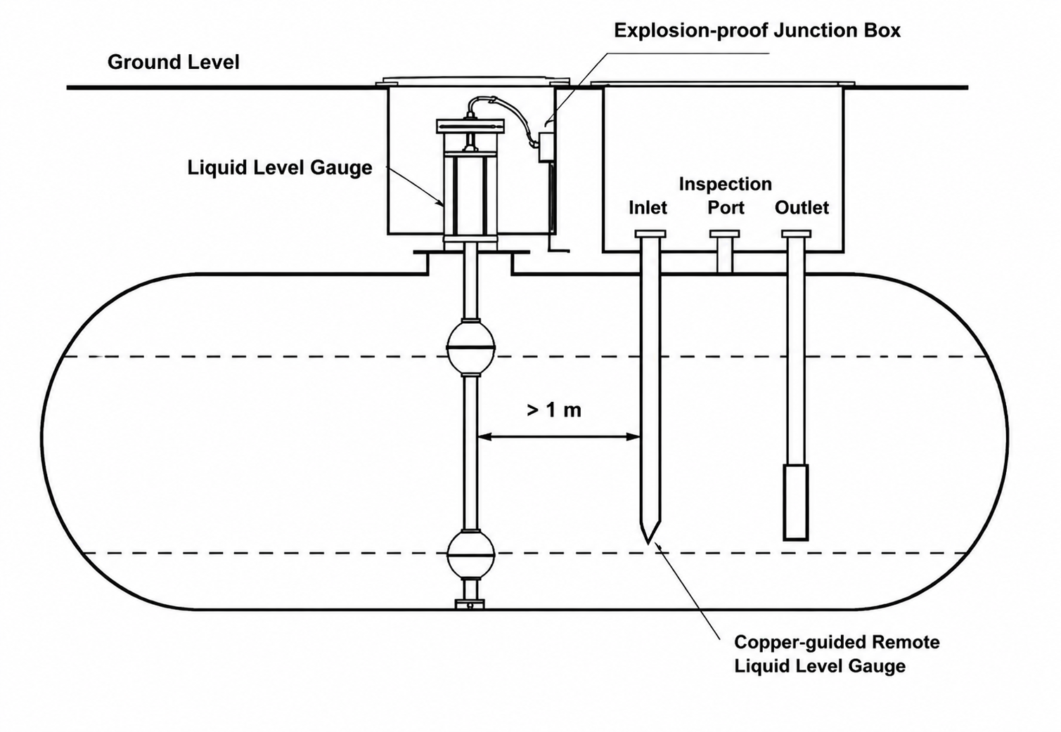
The installation position of the level gauge must maintain a safe distance from other tank components.
The distance between:
- Level gauge
- Fuel unloading pipe
- Submersible pump
should be not less than 1 meter.
If the distance is too close, the strong fuel flow impact during unloading may affect measurement accuracy or even damage the level probe.
During construction, the direction of the fuel inlet pipe should be adjusted so that the fuel flow direction is away from the level gauge probe.
This prevents direct impact on:
- Probe rod
- Float
- Measuring components
- Upper Extension Pipe Installation Requirements
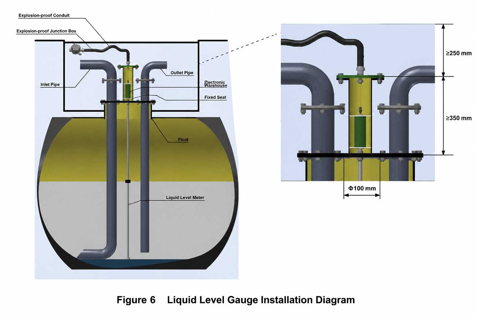
The level gauge uses a vertical installation method.
The requirements are:
- Upper extension pipe specifications:
- Pipe size: DN100 seamless steel pipe (4 inches)
- Installation direction: Vertical installation
- Pipe inner wall: Smooth and free of burrs
- Pipe extension above manhole cover: ≥350 mm
If the extension pipe enters the manhole cover area:
- The insertion length should not exceed 100 mm.
The flange design should match the level gauge installation structure.
The pipe must remain vertical because any tilt may affect:
- Fuel height measurement
- Tank capacity calculation accuracy
- Manhole Construction Requirements
The manhole area is an important part of the tank monitoring system installation.
Correct construction ensures:
- Easy maintenance access
- Waterproof protection
- Explosion-proof safety
Manhole requirements:
- Manhole size
The opening should be:
≥800mm × 800mm
This allows technicians to install and maintain equipment safely.
- Waterproof protection
The outside wall of the manhole should be:
Higher than 300mm
This prevents:
- Rainwater entering the manhole
- Flooding damage
- Moisture affecting electrical equipment
- Installation space
The distance between:
Manhole cover → Level gauge flange
should be:
≥250mm
This provides enough space for installing explosion-proof flexible conduits and cable connections.
- Grounding requirements
The grounding flat iron should:
- Extend from the manhole wall ≥100mm
- Recommended specification: 40×4mm
- Equipped with M8 grounding bolt
The grounding resistance should be:
Less than 4Ω
The grounding system must be reliably connected to the station grounding network.
- Communication Cable Installation Requirements
Reliable communication is essential for accurate tank monitoring.
The communication cable installation must follow these requirements:
Protective Pipe Installation
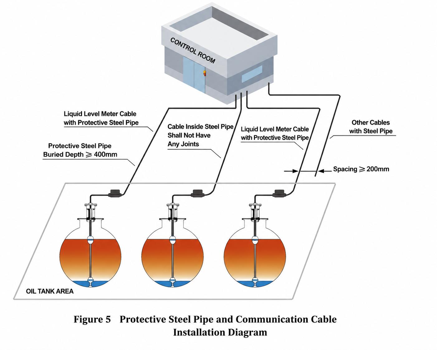
All level gauge communication cables must be installed inside protective steel pipes.
Recommended pipe:
- DN15 or DN20 galvanized steel pipe
Installation requirements:
Underground installation depth:
≥400mm
Backfilling requirements:
- Use fine sand or soft soil
- Backfill thickness ≥100mm
The protective pipe must:
- Have a smooth internal surface
- Have no sharp edges
- Avoid damaging communication cables
Cable Requirements
Communication cable requirements:
Recommended cable:
RVVP 4×0.5mm² shielded cable or above
Requirements:
- One complete cable from controller to tank
- No cable joints allowed
- Shield layer must be properly grounded
Recommended communication distance:
Less than 300 meters
Maximum communication distance:
1200 meters
Communication method:
RS-485
The cable capacitance requirement:
≤100pF/300mm
Grounding Requirements
Both ends of the protective steel pipe must have grounding terminals.
Recommended:
- M6 grounding bolt
- M8 grounding bolt
The grounding wire should be securely connected to the fuel station grounding system.
- Level Gauge Installation Procedure
Because the magnetostrictive level gauge is a high-precision measuring device, careful handling is required during installation.
Installation steps:
Step 1: Check components
Remove:
- Level gauge
- Connector cable
- Float components
Check for:
- Damage
- Missing parts
- Deformation
Step 2: Record equipment information
Record the:
Factory serial number
from the nameplate.
This number is required for:
- Communication configuration
- System identification
- After-sales service
Step 3: Install floats
Install:
- Fuel float
- Water float
at the bottom of the probe rod.
Step 4: Install electronic head
Install the fixing plate on both ends of the electronic module.
Connect the cable connector and tighten securely.
Step 5: Remove magnetic influence
Slowly move the float up and down:
2–3 times
This helps remove magnetic interference and ensures stable measurement.
Step 6: Insert into tank
Carefully place the probe into the tank through the extension pipe.
Important:
- Keep the probe vertical
- Do not pull the communication cable
- Avoid impact damage
Installation tools should be:
Copper tools or explosion-proof tools
to prevent sparks in hazardous areas.
- Explosion-Proof Flexible Conduit and Junction Box Installation
Because the fuel tank monitoring system is installed in a hazardous area where fuel vapor may exist, all wiring connections must meet explosion-proof installation requirements.
Incorrect installation of explosion-proof components may cause:
- Fuel vapor leakage
- Electrical failure
- Loss of explosion protection
- Potential safety risks
Before installation:
The power supply must remain disconnected until the entire system installation is completed and checked.
Installation Requirements for Explosion-Proof Components
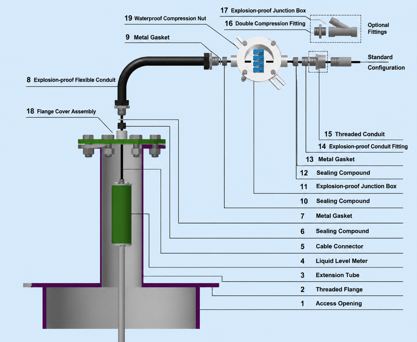
All components must be installed according to the correct sequence.
Installation requirements:
- Correct installation order
All explosion-proof parts must be installed in the correct order.
Do not:
- Reverse components
- Remove explosion-proof structures
- Replace original safety components without approval
- Sealing protection
The explosion-proof isolation sealing box must be completely filled with explosion-proof sealing compound.
Purpose:
- Prevent fuel vapor from entering the control room through the protective pipe
- Maintain explosion-proof performance
- Cable sealing
Cable sealing components must tightly compress the cable.
This prevents:
- Oil vapor leakage
- Moisture entering the system
- Cable movement
- Tightening requirements
All parts must be properly tightened:
Including:
- Junction box cover
- Cable glands
- Pipe connections
- Flange connections
- Grounding requirements
The junction box and protective pipe must have reliable grounding.
Grounding cable:
Cross-sectional area ≥6mm²
The grounding system must connect to the fuel station grounding network.
- Flange grounding connection
When tightening the upper extension pipe flange and flange cover:
A grounding copper bridge must be installed.
This ensures electrical continuity and improves safety.
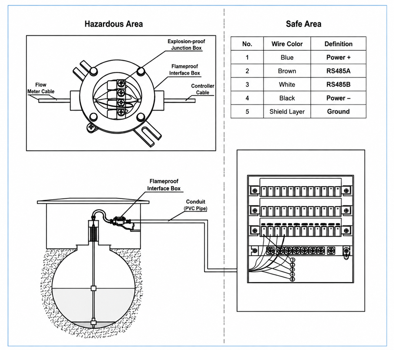
- Electrical Wiring Requirements of Tank Level Monitoring System
The cable from the level gauge must be correctly connected to the safety barrier terminals inside the controller.
The cable shield layer must connect to the grounding terminal of the safety barrier.
The safety barrier must be reliably connected to the fuel station grounding system.
Safety Barrier Grounding Requirements
The safety barrier grounding terminal must use:
6mm² multi-strand copper wire
to connect reliably to the fuel station grounding system.
Important:
Before all wiring is correctly completed:
Do not supply power to the system.
Incorrect wiring may cause:
- Communication failure
- Safety barrier damage
- System malfunction
- Controller Installation Requirements
The controller should be installed in a safe area.
Recommended locations:
- Control room
- Office
- Electrical cabinet room
The controller should not be installed directly in hazardous areas.
Installation requirements:
Mounting
The controller should be:
- Firmly mounted on the wall or installation panel
- Easy for operators to observe and operate
Power Connection
Power supply:
AC220V
The power cable must be connected correctly.
After confirming:
- Wiring is correct
- Grounding is reliable
- All components are installed properly
Only then can the system be powered on.
- Common Problems and Troubleshooting
During daily operation, fuel station operators may encounter communication problems, display problems, or measurement errors.
Below are common failures and solutions.
| Problem | Possible Cause | Solution |
|---|---|---|
| Communication failure | Communication cable disconnected or wrong wiring sequence | Check RS-485 wiring and cable connection |
| Communication failure | Safety barrier failure | Replace safety barrier |
| Communication failure | Level probe failure | Check or replace level probe |
| Incorrect time display | Incorrect system setting | Reset system time |
| Incorrect time display | Battery power low | Replace battery |
| Black screen | Screen saver activated | Touch screen or restart system |
| Black screen | Backlight or display failure | Replace display module |
| Cannot connect to management software | Wrong communication settings | Check software configuration |
| Cannot connect to management software | RS-232 cable problem | Check communication cable |
| No display or no response | Power failure | Check AC power supply |
| No display or no response | Fuse damaged | Replace fuse |
| No display or no response | Power module failure | Replace power module |
- Daily Maintenance Recommendations
Although magnetostrictive level gauges require little maintenance, regular inspection can significantly improve system reliability.
Recommended maintenance:
- Check communication status regularly
Confirm:
- Controller receives normal data
- Fuel level updates correctly
- No communication alarms appear
- Inspect grounding system
Regularly check:
- Grounding connections
- Junction box grounding
- Protective pipe grounding
Poor grounding may cause:
- Signal interference
- Communication instability
- Check explosion-proof components
Inspect:
- Junction box sealing
- Cable glands
- Flexible conduits
Make sure:
- No damage exists
- No loose connection occurs
- Sealing remains effective
- Verify measurement accuracy
Compare:
- Displayed fuel level
- Actual tank level
If abnormal differences appear:
Check:
- Probe vertical installation
- Float movement
- Communication settings
- Keep installation records
Maintain records including:
- Equipment serial number
- Installation date
- Maintenance history
- Replacement parts
This helps improve troubleshooting efficiency and after-sales service.
- Professional Installation Tips for Better System Performance
To ensure stable operation of a fuel station tank monitoring system, several key points should always be remembered:
✔ Keep the probe vertical
A tilted probe may affect:
- Fuel height calculation
- Inventory accuracy
✔ Protect communication cables
Avoid:
- Cable joints
- Mechanical damage
- Excessive bending
✔ Maintain reliable grounding
Good grounding is essential for:
- Explosion protection
- Communication stability
- Equipment safety
✔ Follow explosion-proof requirements
Never:
- Modify safety components
- Replace certified parts randomly
- Ignore grounding requirements
- Summary
A high-quality fuel tank level monitoring system provides accurate measurement, better inventory management, and improved safety for modern gas stations.
Correct installation, proper wiring, reliable grounding, and regular maintenance are the key factors that ensure long-term stable operation.
By following professional installation standards and safety requirements, operators can reduce failures, improve efficiency, and create a safer fuel station environment.
By integrating equipment supply, technical support, and project experience, fuel station operators can build safer, more efficient, and more reliable petroleum service systems.
Learn more about our fuel station equipment supply chain services and how we support equipment sourcing, technical coordination, and project requirements.