
Fuel Dispenser Installation Guide: Piping, Electrical, Grounding and Safety Requirements
News 2026年 9月 5日 85
Introduction
Why can a fuel dispenser rated at 50 L/min deliver less than 50 L/min? Why can a properly powered dispenser still fail a grounding test? And what happens if the emergency shutdown works at the button but does not stop the fuel supply?
Fuel dispenser installation is not simply a matter of connecting a power cable and a fuel pipe.
The actual performance and safety of a dispenser depend on several connected systems:
Fuel Pump → Underground Piping → Fuel Dispenser → Hose & Nozzle → Electrical System → Grounding → Emergency Shutdown
A problem in any one of these systems can affect the complete fueling system.
This guide focuses on the engineering parameters that matter during fuel dispenser installation, including flow demand, pipe diameter, electrical configuration, grounding resistance, pipeline bonding, hazardous-area wiring, shear valves, breakaway valves and pre-commissioning tests.
Standards Note
The technical values and installation practices presented in this article are primarily based on Chinese gas station engineering standards and commonly used construction practices in China. They are provided as engineering reference values for overseas projects.
For projects outside China, the final design, installation and acceptance criteria should comply with the applicable local electrical, fire protection, hazardous-area, petroleum and environmental regulations, together with the fuel dispenser manufacturer’s installation instructions.
Therefore, the values in this guide should be used as a technical reference rather than a universal international standard.
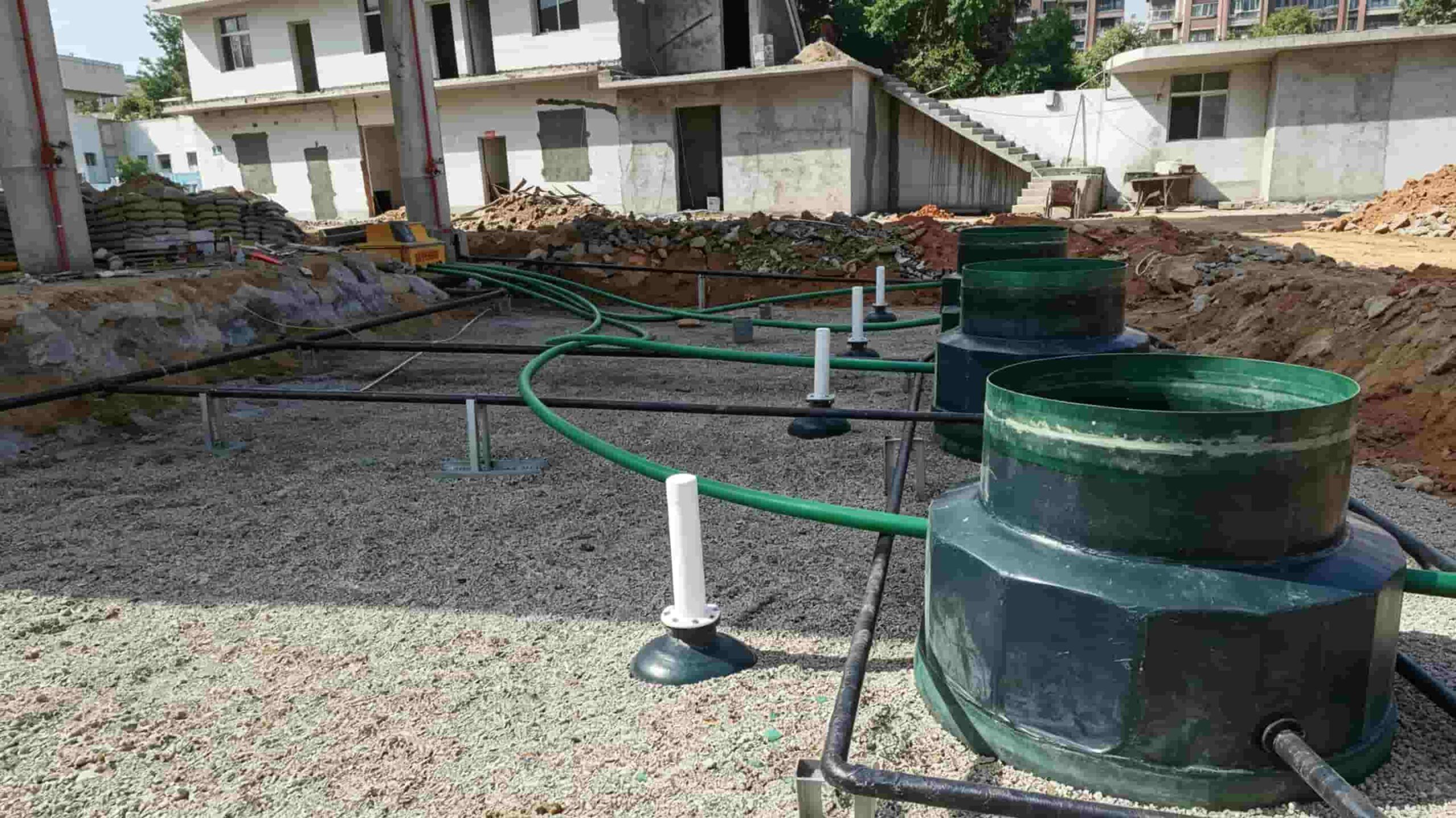
1. Five Numbers to Check Before Fuel Dispenser Installation
Before installing a fuel dispenser, five basic parameters determine whether the complete system can deliver the required fueling performance.
| Parameter | Why It Matters |
|---|---|
| Dispenser flow rate | Determines the required fuel supply capacity |
| Number of fueling positions | Determines peak simultaneous demand |
| Pipeline length | Affects pressure loss |
| Pipe diameter | Affects flow capacity and pressure drop |
| Pump capacity | Must support the required fuel demand |
The most important point is that dispenser flow rate should not be evaluated independently from the pump and piping system.
For example, suppose a dispenser has four fueling positions and each position is designed for 40 L/min.
The theoretical maximum demand is:
40 L/min × 4 = 160 L/min
However, this does not automatically mean that a 160 L/min pump is sufficient.
The actual system must also consider:
- Pipeline length
- Pipe diameter
- Number of elbows and valves
- Filter resistance
- Pressure loss
- Simultaneous fueling
- Pump performance
A practical engineering relationship is:
Required Pump Capacity ≥ Simultaneous Fueling Demand + System Pressure Loss Allowance
This is why the dispenser, pump and underground piping should be selected as one system.
See our Fuel Dispenser Product Range to compare different dispenser configurations and models.
2. Fuel Dispenser Piping: Flow Rate, Pipe Diameter and Pressure Loss
A fuel dispenser’s rated flow does not necessarily equal the actual flow delivered at the nozzle.
The complete fuel path can be simplified as:
Underground Tank → Pump → Main Fuel Pipe → Branch Pipe → Dispenser → Meter → Hose → Nozzle
Every component along this path can affect the final fueling rate.
2.1 Why Does Actual Flow Become Lower?
Common causes include:
- Undersized fuel pipe
- Excessive pipeline length
- Too many elbows or fittings
- Insufficient pump capacity
- Multiple dispensers operating simultaneously
- Restricted filters
- Excessive pressure loss
- Incorrect valve selection
For example, if a dispenser is rated at 50 L/min, but the pump and piping system cannot maintain the required pressure and flow, the actual nozzle flow may be significantly lower.
This means:
A 50 L/min dispenser is not a guarantee of 50 L/min actual fueling performance.
The complete hydraulic system must be evaluated.
To understand how rated flow, pump capacity and actual fueling demand affect dispenser selection, see our [Fuel Dispenser Flow Rate] guide.
2.2 Pipe Diameter Should Match the Required Flow
Pipe diameter should be selected according to:
- Required flow rate
- Number of fueling positions
- Simultaneous fueling demand
- Pump capacity
- Pipeline length
- Fittings and valves
- Allowable pressure loss
A larger pipe is not always necessary, while an undersized pipe can create unnecessary pressure loss.
For a detailed discussion of pipe diameter, layout, burial depth and underground installation, see our guide to [Gas Station Underground Fuel Piping].
2.3 Multiple Dispensers Need Special Attention
Suppose one underground pump supplies three dispensers.
If several nozzles are used simultaneously, the total fuel demand can increase rapidly.
For example:
4 nozzles × 40 L/min = 160 L/min
If another dispenser is operating from the same supply system, the required pump and main pipe capacity may need to be increased accordingly.
Therefore, the number of nozzles alone cannot determine pump size or pipe diameter.
3. 220V vs. 380V: How Should the Electrical Configuration Be Determined?
Should a fuel dispenser use 220V or 380V?
This is one of the most common questions during fuel dispenser installation.
The answer should not be based simply on whether the dispenser has two, four, six or eight nozzles.
The electrical configuration depends on:
- Dispenser model
- Motor/pump configuration
- Total electrical load
- Local power supply
- Single-phase or three-phase system
- Cable length
- Voltage drop
- Protection device
- Project electrical design
As a general engineering reference:
| Item | 220V | 380V |
|---|---|---|
| Typical supply | Single-phase applications | Three-phase applications |
| Typical application | Smaller electrical loads | Larger electrical loads |
| Pump application | Model dependent | Model dependent |
| Cable configuration | Project dependent | Project dependent |
| Final selection | Local electrical design | Local electrical design |
Therefore:
Do not select 220V or 380V simply according to dispenser size or nozzle quantity.
The correct approach is to calculate the complete electrical load and verify it against the dispenser manufacturer’s specifications and the site’s power supply.
For more information, see our Fuel Dispenser Voltage: 220V vs. 380V guide.
Need Help Choosing the Right Fuel Dispenser Configuration?
Not sure which dispenser model, voltage, nozzle configuration or electrical setup is suitable for your project?
Send us your fuel types, number of fueling positions, power supply and project location. Our team can help you review the equipment configuration.
4. Grounding: Key Resistance Values and Testing
Grounding is not simply a matter of connecting a green/yellow wire to the dispenser body.
The grounding system must provide reliable electrical continuity and meet the required resistance during testing.
The following values can be used as engineering reference values:
| Test Item | Reference Value |
|---|---|
| Overall grounding resistance | ≤4 Ω |
| Pipeline static grounding resistance | ≤30 Ω |
| Flange bonding resistance | ≤0.03 Ω |
| Fuel dispenser body grounding resistance | ≤0.1 Ω |
| Cable insulation resistance | ≥1 MΩ |
| PE conductor reference | ≥6 mm² |
| Grounding flat steel | 40 × 4 mm |
| Typical buried depth | ≥0.8 m |
These values should be verified using appropriate electrical testing equipment.
4.1 Dispenser Body Grounding
The dispenser body should have a reliable protective earth connection.
A proper connection should provide:
- Reliable electrical continuity
- Secure mechanical connection
- Appropriate conductor size
- Corrosion protection
- Accessibility for inspection where required
The grounding contact surface should not be covered by paint or other insulating material.
4.2 Why Resistance Testing Matters
A grounding connection can look correct but still have poor electrical continuity.
For example:
Physical connection ≠ Qualified electrical connection
This is why visual inspection alone is insufficient.
The grounding system should be tested before commissioning.
5. Pipeline Bonding and Flange Electrical Continuity
Metallic fuel pipelines may contain components that interrupt electrical continuity.
Typical examples include:
- Flanges
- Insulating gaskets
- Coatings
- Flexible connections
- Dissimilar metal connections
A pipeline can therefore be mechanically continuous while its electrical continuity is interrupted.
Where electrical continuity is interrupted, an appropriate bonding jumper or other approved bonding method may be required.
As an engineering reference, a 6 mm² or larger bonding conductor may be used for relevant metallic pipeline bonding applications.
For long metallic pipelines, additional bonding or grounding points may be arranged at approximately 20–30 m intervals, depending on the grounding design.
The reference test value for flange bonding resistance is:
≤0.03 Ω
Before underground piping is covered, check:
- Pipeline electrical continuity
- Flange bonding
- Bonding conductor connection
- Corrosion protection
- Mechanical protection
This is particularly important because problems hidden underground can become difficult and expensive to correct later.
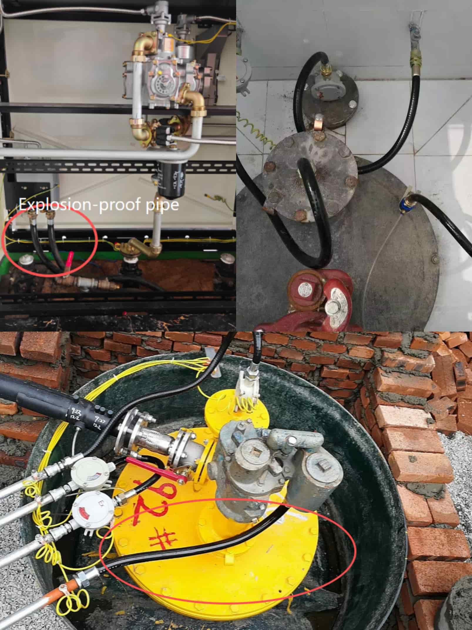
6. Hazardous-Area Wiring and Explosion-Proof Connections
Fuel dispensers are installed in environments where flammable fuel vapor may be present.
Electrical equipment installed in classified hazardous areas therefore requires appropriate equipment, wiring methods and sealing systems.
Depending on the project, this can involve:
- Explosion-proof electrical equipment
- Galvanized steel conduit
- Explosion-proof flexible conduit
- Approved cable glands
- Sealing fittings
- Junction boxes
- Hazardous-area certified equipment
- Strong-current and weak-current separation
In relevant Chinese project installation practices, galvanized steel conduit and approved explosion-proof flexible connections may be used.
Where threaded steel connections are used, at least six effective threads of engagement can be used as an installation reference, subject to the equipment and project requirements.
As project reference values:
- Power cable: ≥2.5 mm²
- Communication cable: ≥1.0 mm²
However, the final conductor size should be determined according to actual load, voltage drop, protective device, installation method and applicable electrical requirements.
Cable Entry Sealing
Cable entries are more than simple mechanical openings.
An improperly sealed cable entry can allow water, dust or fuel vapor to enter the equipment and may compromise the intended protection level.
Therefore, cable glands, seals and fittings should be suitable for the equipment and installation environment.
7. Shear Valve vs. Breakaway Valve: Two Different Safety Functions
Shear valves and breakaway valves are sometimes confused because both are associated with fuel dispenser safety.
However, they perform different functions.
| Device | Main Function | Typical Location |
|---|---|---|
| Shear valve | Helps stop fuel supply after severe dispenser impact | Fuel supply line near dispenser |
| Breakaway valve | Separates the hose connection under excessive pulling force | Hose assembly |
7.1 Shear Valve
In applicable pressure-fed systems, the shear valve is installed in the fuel supply line near the dispenser.
Its purpose is to help interrupt fuel flow if the dispenser is severely impacted or displaced.
The installation position should allow the valve to perform its intended safety function.
7.2 Breakaway Valve
The breakaway valve is normally associated with the hose assembly.
If a vehicle moves away while the nozzle or hose is still connected, excessive pulling force can occur.
The breakaway mechanism is designed to separate under the specified conditions and help limit fuel release.
Therefore:
Shear Valve ≠ Breakaway Valve
They should not be considered interchangeable safety devices.
Need a Complete Fuel Dispenser Installation Solution?
Fuel dispenser installation involves more than the dispenser itself. Pumps, underground piping, hoses, safety valves, electrical systems and grounding all need to work together.
Share your project requirements with us, and we can help you review the complete equipment configuration.
8. Emergency Shutdown: How to Verify the System Actually Works
Installing an emergency stop button is not enough.
The complete emergency shutdown circuit should be tested during commissioning.
Depending on the project, emergency shutdown points may include:
- Individual dispenser emergency stop
- Remote emergency stop
- Control room or cashier-area emergency stop
- Pump shutdown control
A basic functional test should verify:
Emergency Stop Activated
↓
Dispenser Stops
↓
Relevant Pump Stops
↓
Control System Receives Shutdown Signal
↓
Alarm / Indicator Operates
↓
Manual Reset
The exact sequence depends on the station control system.
The important point is that the emergency shutdown function should be tested as a complete system rather than checking only whether the button physically moves.
9. Pre-Commissioning: 10 Tests Before Fueling Starts
Before a new fuel dispenser begins operation, the following checks should be completed.
| No. | Test | Reference / Check |
|---|---|---|
| 1 | Grounding resistance | ≤4 Ω reference |
| 2 | Flange bonding | ≤0.03 Ω reference |
| 3 | Dispenser grounding | ≤0.1 Ω reference |
| 4 | Hose resistance | 10⁴–10⁶ Ω reference |
| 5 | Cable insulation | ≥1 MΩ reference |
| 6 | Pipeline pressure/leak test | Qualified |
| 7 | Shear valve | Correct position and function |
| 8 | Emergency shutdown | Functional test completed |
| 9 | Nozzle automatic shutoff | Tested |
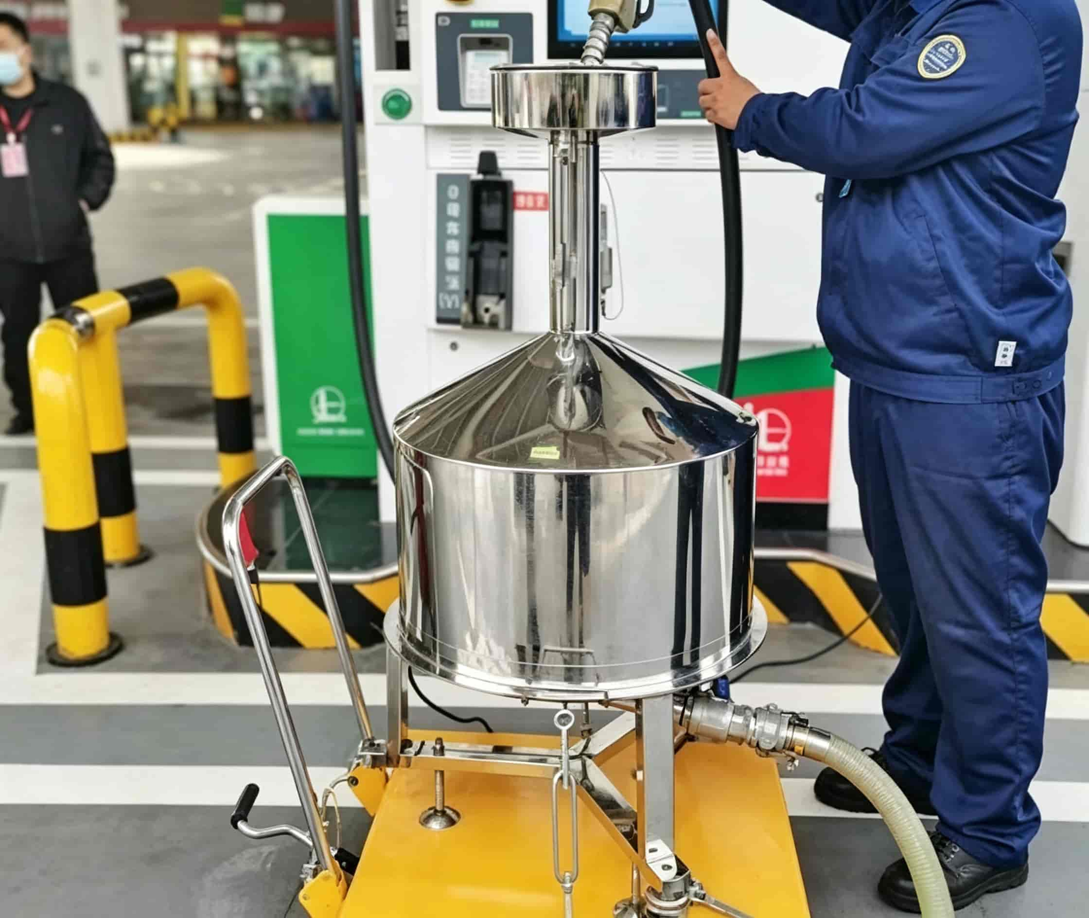
| 10 | Dispenser calibration | Verified |
These tests should be documented as part of the commissioning records.
Why Is This Important?
A dispenser can appear completely normal during visual inspection but still fail an electrical, hydraulic or safety test.
For example:
- Ground wire connected → but resistance is too high
- Pipe connected → but leakage test fails
- Dispenser powers on → but emergency shutdown does not stop the system
- Nozzle dispenses fuel → but actual flow is below the expected value
- Cable installed → but insulation resistance is insufficient
Commissioning is therefore the stage where the complete system must be verified.
10. Installation Mistakes That Visual Inspection Cannot Detect
Mistake 1: PE Is Connected but Grounding Resistance Is Not Qualified
A visible grounding wire does not prove that the grounding system is electrically qualified.
Solution: Perform the required resistance and continuity tests.
Mistake 2: Pipeline Is Mechanically Connected but Electrical Continuity Is Poor
A flange can be physically tight while electrical continuity is interrupted by insulating gaskets, coatings or other components.
Solution: Check bonding continuity and resistance.
Mistake 3: Dispenser Powers On but Emergency Shutdown Does Not Stop the Pump
Electrical power availability does not prove that the safety circuit works.
Solution: Test the complete emergency shutdown circuit.
Mistake 4: Dispenser Rated at 50 L/min but Actual Flow Is Much Lower
The rated dispenser flow does not automatically mean the complete fuel supply system can deliver the same flow.
Solution: Check pump capacity, pipe diameter, pipeline length, fittings and simultaneous demand.
Mistake 5: Cable Entry Is Installed but Not Properly Sealed
An apparently complete cable installation can still have inadequate sealing.
Solution: Check cable glands, sealing fittings and equipment protection requirements.
11. Practical Fuel Dispenser Installation Sequence
For a new station project, the installation can be organized into the following sequence:
1. Confirm dispenser model and fuel configuration
↓
2. Confirm pump capacity and expected simultaneous demand
↓
3. Verify underground piping and pipe diameter
↓
4. Install dispenser base and fuel connections
↓
5. Install shear valve where applicable
↓
6. Complete electrical power and PE connections
↓
7. Complete grounding and pipeline bonding
↓
8. Install hazardous-area wiring and cable sealing
↓
9. Connect hoses, breakaway valves and nozzles
↓
10. Test emergency shutdown
↓
11. Perform electrical, grounding and leak tests
↓
12. Calibrate and commission the dispenser
This sequence helps reduce the risk of discovering installation problems after the equipment has already been fully assembled.
12. FAQ
1. What grounding resistance should a fuel dispenser have?
As a Chinese engineering reference, overall grounding resistance can be controlled at ≤4 Ω, while dispenser body grounding can use ≤0.1 Ω as a reference value. Final acceptance requirements should follow the applicable local regulations and project specifications.
2. Why can a 50 L/min fuel dispenser deliver less than 50 L/min?
Because actual fueling flow depends on the complete hydraulic system. Pump capacity, pipe diameter, pipeline length, fittings, filters, pressure loss and simultaneous fueling demand can all reduce actual flow.
3. Should a fuel dispenser use 220V or 380V?
The choice depends on the dispenser model, electrical load, pump configuration, local power supply and project electrical design. Nozzle quantity alone should not be used to determine the voltage.
4. What is the difference between a shear valve and a breakaway valve?
A shear valve is associated with the fuel supply connection and helps interrupt fuel flow after severe dispenser impact. A breakaway valve is normally installed in the hose assembly and separates under excessive pulling force.
5. What cable size is used for a fuel dispenser?
As project reference values, a power cable of ≥2.5 mm² and communication cable of ≥1.0 mm² may be used. Final cable sizing must consider actual load, voltage drop, protection and local electrical requirements.
6. How do you test fuel dispenser grounding before commissioning?
Grounding resistance and electrical continuity should be measured with appropriate test equipment. Connections should also be visually inspected for secure mechanical contact, corrosion and proper bonding.
7. What should be tested before a new fuel dispenser starts operating?
The commissioning process should include grounding, bonding, cable insulation, pipeline leak/pressure testing, shear valve function, emergency shutdown, nozzle automatic shutoff and dispenser calibration.
13. Conclusion
Fuel dispenser installation is a system engineering task rather than a simple equipment connection.
The critical relationships are:
Flow Rate → Pump Capacity → Pipe Diameter → Electrical Supply → Grounding → Hazardous-Area Protection → Emergency Shutdown → Commissioning
A dispenser should therefore be evaluated together with its pump, underground piping, electrical system and safety equipment.
Using measurable engineering parameters during installation and commissioning helps identify problems that cannot be detected through visual inspection alone.
Get a Fuel Dispenser Solution for Your Project
Planning a new gas station or upgrading an existing fueling system?
Send us your fuel types, required flow rate, number of fueling positions, dispenser quantity, power supply and project location.
Our team can help you review the dispenser configuration, pump matching and related fuel station equipment requirements.