
Gas Station Fuel Leak Detection System: Tanks, Piping and Sensors
News 2026年 8月 18日 68
Introduction
How can a gas station detect a fuel leak before it reaches the surrounding soil?
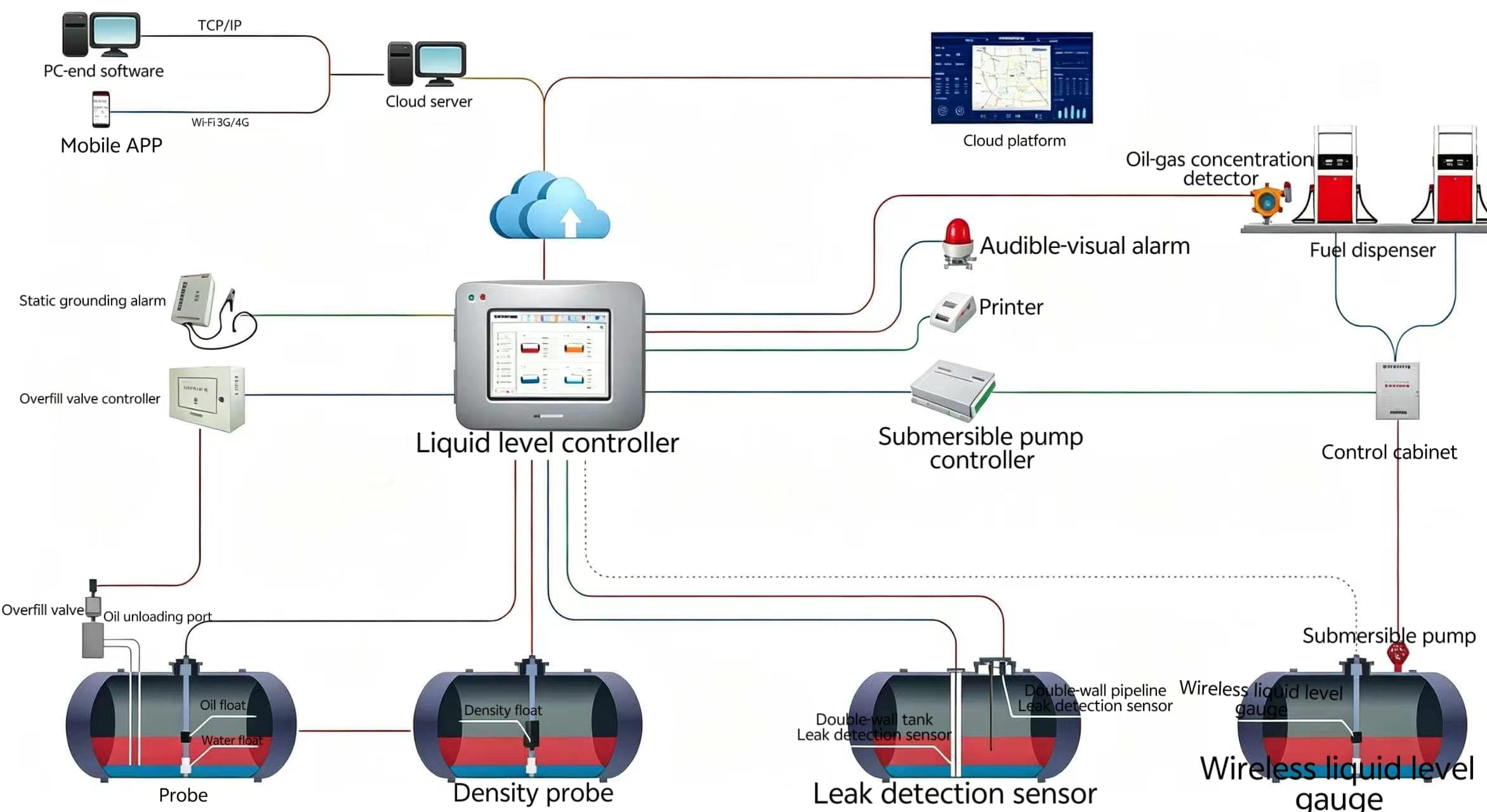
A reliable fuel leak detection system is not simply a sensor installed inside a tank or sump. It combines secondary containment, leak detection points, sensors and online monitoring to identify leakage from underground fuel tanks, piping, tank manholes and dispenser sumps.
For underground fuel systems, the basic principle is:
Contain the leakage → guide it to a detection point → detect the liquid → send an alarm.
Under GB 50156-2021, underground fuel tanks and piping are required to use specific anti-seepage measures, while online monitoring is recommended for leak detection in double-wall tanks, secondary containment tank pits and double-wall piping.
This article explains the main leak detection methods, installation requirements and technical parameters that gas station owners, contractors and equipment buyers should understand.
1. Where Can Fuel Leakage Occur?
Fuel leakage can occur at several points in an underground fueling system.
| Potential Leakage Area | Protection / Detection Method |
|---|---|
| Underground fuel tank | Double-wall tank or secondary containment tank pit |
| Secondary containment tank pit | Detection riser + liquid sensor |
| Double-wall fuel piping | Interstitial monitoring + leak detection point |
| Tank manhole / STP sump | Secondary containment + leak sensor |
| Unloading connection well | Appropriate anti-seepage protection |
| Fuel dispenser sump | Secondary containment + liquid sensor |
The purpose of secondary containment is not only to prevent fuel from entering the surrounding soil. It also creates a controlled space where leakage can be collected and detected.
This is why containment design and leak detection should be considered together rather than as two completely separate systems.
2. Secondary Containment for Underground Fuel Tanks
Underground fuel tanks should use one of the following anti-seepage methods:
- Double-wall fuel tank
- Single-wall fuel tank installed inside a secondary containment tank pit
A double-wall tank provides a space between the inner and outer walls where leakage can be detected.
For a single-wall tank, the secondary containment tank pit provides the additional barrier required to prevent leaked fuel from directly entering the surrounding soil.
Secondary Containment Tank Pit Requirements
According to GB 50156-2021, the secondary containment tank pit should meet several engineering requirements.
Reinforced Concrete Structure
The tank pit should use integrally cast impermeable reinforced concrete and comply with the relevant requirements of GB 50108.
Tank Quantity
The containment tank pit should be divided into separate compartments according to the number of tanks.
No more than two tanks should be installed in one compartment.
Tank-to-Wall Clearance
The bottom of the tank pit should preferably be:
200 mm below the designed elevation of the tank bottom.
The distance between the containment wall and tank wall should be:
≥500 mm
Internal Anti-Seepage Layer
The inner surface of the containment tank pit should be lined with fiberglass or another suitable impermeable material.
Backfill
The internal space of the secondary containment tank pit should be backfilled with neutral sand.
Protection Against External Water and Fuel
The upper part of the tank pit should prevent:
- Rainwater
- Surface water
- External leaked fuel
from entering the containment space.
These measures create the physical foundation for subsequent leak detection.
3. Leak Detection Riser for Secondary Containment Tank Pits
A secondary containment structure can prevent fuel from immediately reaching the soil, but the leakage still needs to be detected.
For this reason, each compartment of a secondary containment tank pit should have a leak detection riser.
The riser provides a defined path for leaked liquid to reach the detection point.
Key Detection Riser Requirements
| Parameter | Requirement |
|---|---|
| Material | Oil-resistant and corrosion-resistant |
| Recommended diameter | 100 mm |
| Minimum wall thickness | 4 mm |
| Riser top above designed ground level | 200 mm |
| Gravel particle size around riser | 10–30 mm |
The lower end of the detection riser should be located at the lowest point of the secondary containment tank pit.
The section below the tank top elevation should be a filtered section. It should allow leakage from different levels inside the tank pit to enter the detection riser while preventing sand and other debris from entering.
The area around the detection riser should be backfilled with 10–30 mm gravel.
The detection opening should also have a protective cover and identification marking to prevent rainwater, oil and debris from entering.
4. Leak Detection for Double-Wall Underground Fuel Piping
Underground fuel piping is another important potential leakage source.
Proper pipe selection, routing and installation are therefore essential for preventing fuel leakage. See our guide to underground fuel piping for more details.
For gas stations using underground fuel piping, GB 50156-2021 specifies the use of double-wall piping.
The inner pipe should meet the applicable requirements, while the outer pipe should provide additional protection against fuel leakage.
For double-wall non-metallic piping, the outer pipe should meet the requirements for:
- Oil resistance
- Corrosion resistance
- Aging resistance
- System test pressure
For double-wall steel piping, the outer pipe wall thickness should be:
≥5 mm
Interstitial Space
The space between the inner and outer pipes should be continuous.
The lowest point of the double-wall piping system should have a leak detection point.
The piping should slope toward this detection point at:
≥5‰
The design should ensure that leakage occurring at any part of either the inner or outer pipe can be detected at the designated detection point.
For this reason, online monitoring is recommended for double-wall piping systems.
The basic structure can be understood as:
Inner Pipe → Interstitial Space → Lowest Point → Leak Detection Point → Online Monitoring
5. How Does a Gas Station Fuel Leak Detection System Work?
A complete leak detection process can be divided into five steps.
Step 1: Containment
The leaked fuel is contained by:
- Double-wall tanks
- Secondary containment tank pits
- Double-wall piping
- Dispenser sumps
- STP sumps and other containment structures
Step 2: Leakage Collection
The containment structure provides a controlled space for leaked liquid to collect.
For a tank pit, the liquid is guided toward the lowest point and detection riser.
For double-wall piping, the interstitial space guides leakage toward the leak detection point.
Step 3: Sensor Detection
A liquid sensor identifies the presence of leaked liquid.
Depending on the system, different detection principles can be used.
Step 4: Online Monitoring
The sensor sends a signal to a monitoring controller.
The system can continuously monitor the detection points instead of relying only on periodic manual inspection.
Step 5: Alarm
When leakage is detected, the monitoring system can generate an alarm so that operators can investigate the affected area and take appropriate action.
The basic system logic is:
Containment → Detection Point → Sensor → Controller → Alarm
Leak detection should also be coordinated with the station’s overall equipment and safety design. See our guide to integrated gas station system design for a broader system perspective.
6. Liquid Sensors for Fuel Leak Detection
Liquid sensors are an important part of a gas station leak detection system.
The sensor should be selected according to the installation environment, monitored liquid, explosion-proof requirements and required detection performance.
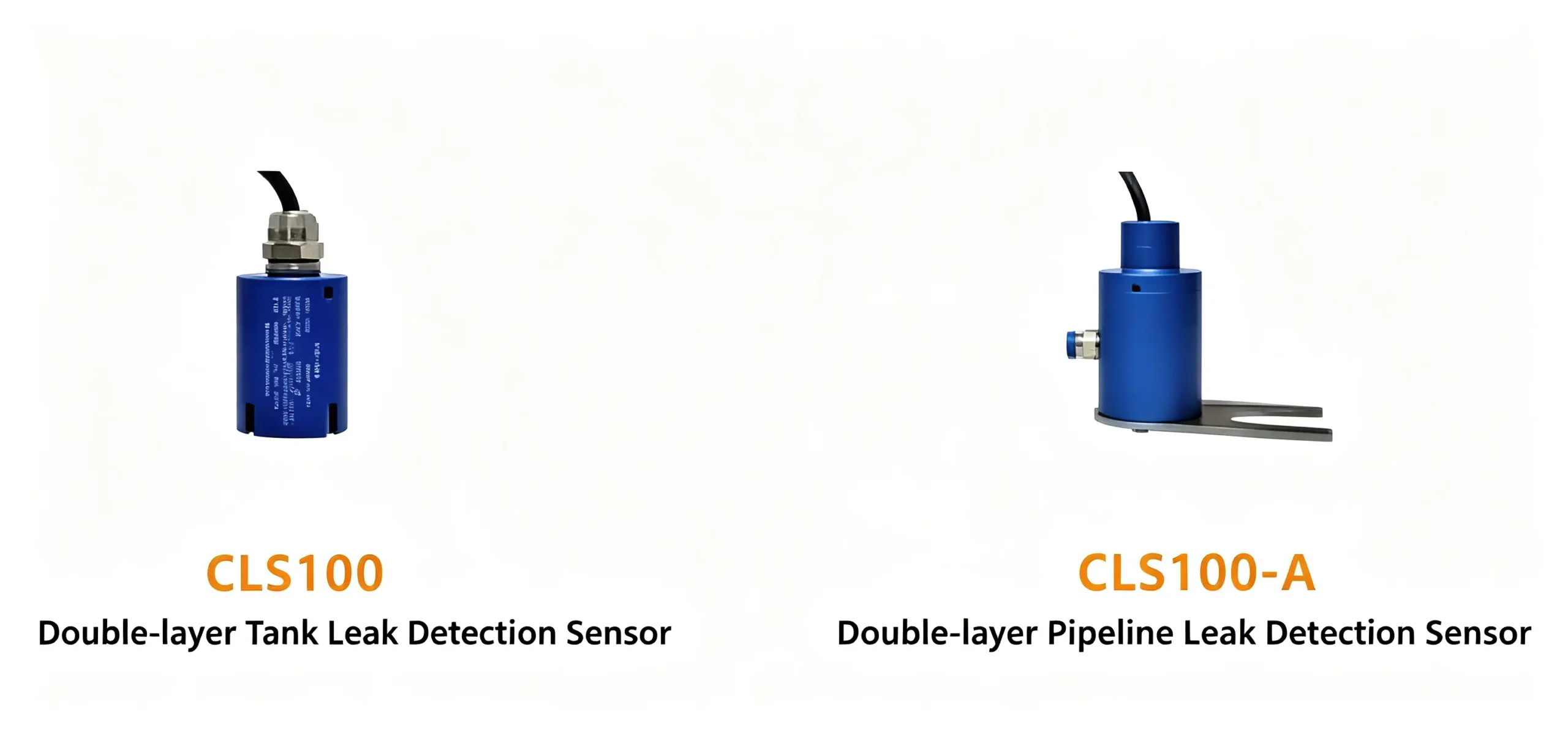
CLS100 Series Liquid Leak Sensors
The CLS100 series uses a float-type detection principle.
When leaked liquid enters the monitored area, the float rises and activates the magnetic mechanism to identify the presence of leakage.
Typical applications include monitoring of fuel leakage in containment spaces.
CLS100 / CLS100-A Technical Parameters
| Parameter | Specification |
|---|---|
| Operating temperature | -40°C ~ 60°C |
| Response time | <2 s |
| Output signal | Switch signal |
| Explosion-proof marking | Ex ib IIA T4 Gb |
The float-type structure is suitable for applications where reliable liquid-level detection is required in a confined monitoring space.
7. CLS200A Series Liquid Leak Sensors
The CLS200A series uses an optical liquid detection principle and can identify oil, water and other liquids in monitored areas.
The series can be used for different monitoring applications, including:
- Double-wall tanks
- Double-wall piping
- Tank manholes
- Dispenser sumps
Different models are available for different installation requirements, including tank, piping, manhole and dispenser sump monitoring.
CLS200A Technical Parameters
| Parameter | Specification |
|---|---|
| Operating temperature | -40°C ~ 60°C |
| Relative humidity | 30% ~ 90% |
| Operating power | DC12V ±0.5V |
| Operating current | <35 mA |
| Response time | <2 s |
| Protection rating | IP68 |
| Explosion-proof marking | Ex ia IIC T4 Ga |
| Sensor communication capacity | Up to 8 sensors |
| Communication distance | Up to 600 m |
For underground applications, the protection rating and explosion-proof specification are particularly important when selecting a liquid leak sensor.
8. Liquid Sensor Detection Accuracy
Sensor sensitivity is another important parameter when designing a leak detection system.
For double-wall fuel tanks and secondary containment tank pits, online monitoring is recommended.
When liquid sensors are used for monitoring, the detection accuracy should be:
≤3.5 mm
This means sensor selection should not only consider whether the sensor can detect liquid, but also whether its detection accuracy satisfies the applicable engineering requirements.
The sensor’s operating temperature, explosion-proof marking, protection rating and response time should also be checked against the actual installation environment.
9. Other Areas Requiring Leakage Protection
Leakage protection should not stop at the underground tank.
GB 50156-2021 also requires appropriate anti-seepage measures for locations where fuel leakage may occur, including:
- Tank manhole operation wells
- Fuel unloading connection wells
- Fuel dispenser sumps
- Other fuel-handling areas where leakage may occur
These areas can use suitable containment and liquid detection arrangements according to the system design.
For example:
Dispenser → Dispenser Sump → Liquid Sensor → Monitoring System
This allows leakage below the dispenser to be detected before it spreads into the surrounding ground.
For more information on dispenser installation and connections, see our guide to fuel dispenser installation, piping and safety connections.
10. Gas Station Leak Detection System: Area vs. Method
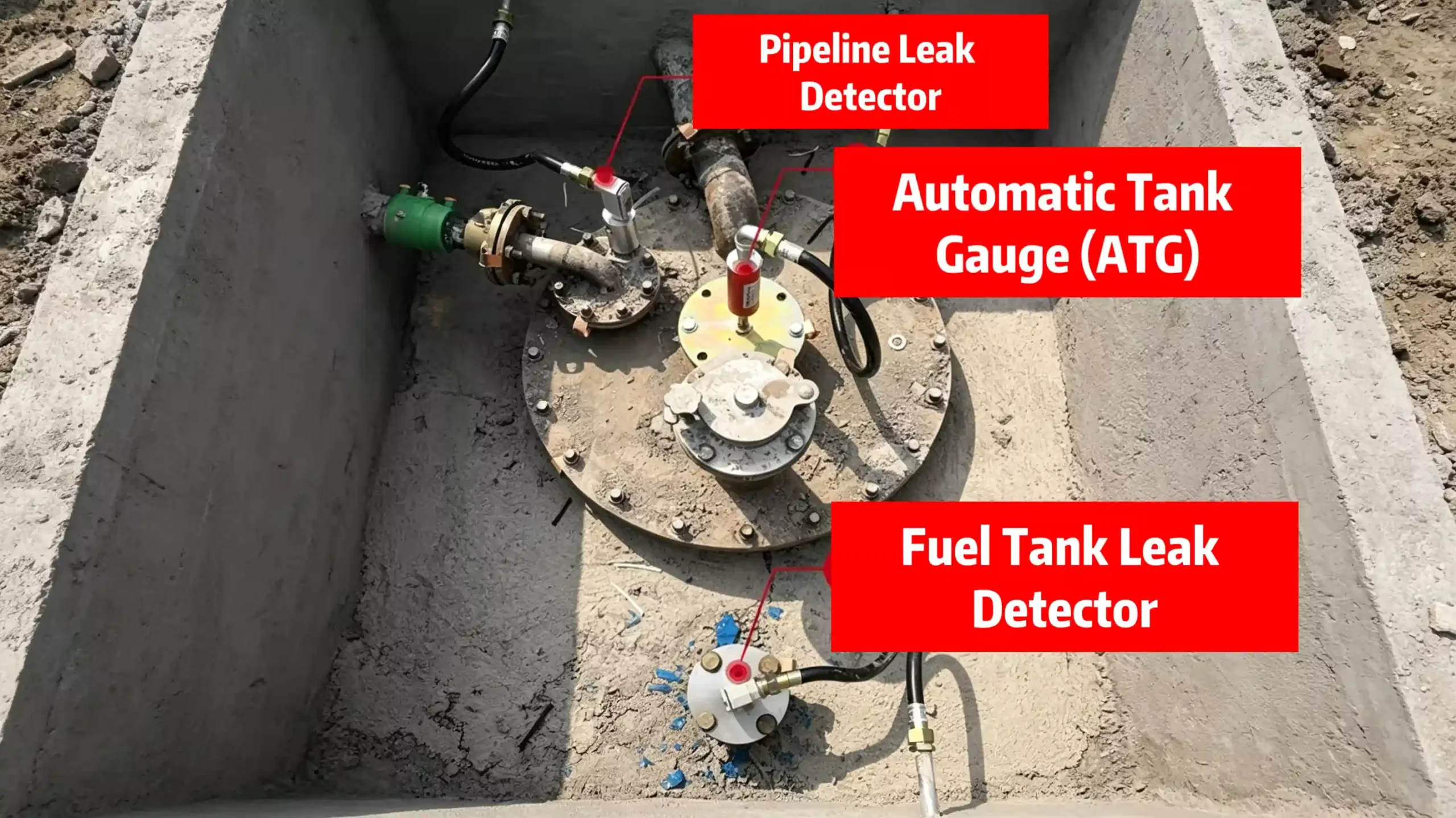
The following table summarizes the relationship between the main fuel system components and their detection methods.
| Area | Containment / Protection | Detection Method |
|---|---|---|
| Double-wall underground tank | Double-wall structure | Interstitial monitoring |
| Single-wall underground tank | Secondary containment tank pit | Detection riser + liquid sensor |
| Double-wall piping | Double-wall structure | Leak detection point + online monitoring |
| Tank manhole / STP sump | Secondary containment | Liquid sensor |
| Fuel dispenser sump | Secondary containment | Liquid sensor |
| Fuel unloading area | Anti-seepage protection | Appropriate monitoring |
| Other leakage-prone areas | Secondary containment | Suitable sensor / monitoring |
This shows an important principle:
A fuel leak detection system should cover the complete path of fuel, from underground storage to the dispenser.
11. Key Parameters to Check Before Selecting a Leak Detection System
When designing or purchasing a gas station fuel leak detection system, buyers should check more than the sensor itself.
For secondary containment
- Tank-to-wall clearance: ≥500 mm
- Tank pit bottom: preferably 200 mm below tank bottom elevation
- Detection riser diameter: 100 mm
- Detection riser wall thickness: ≥4 mm
- Gravel around detection riser: 10–30 mm
For double-wall piping
- Outer pipe wall thickness for double-wall steel piping: ≥5 mm
- Interstitial space: continuous
- Leak detection point: at the lowest point
- Pipe slope toward detection point: ≥5‰
- Online monitoring: recommended
For liquid sensors
- Detection accuracy: ≤3.5 mm
- Response time
- Operating temperature
- Explosion-proof marking
- Protection rating
- Power supply
- Communication distance and sensor capacity
The right system is therefore not simply the sensor with the highest specification. The sensor, containment structure, detection point and monitoring controller must work together as one system.
FAQ
What is a fuel leak detection system?
A fuel leak detection system is a combination of containment structures, detection points, sensors and monitoring equipment used to identify fuel leakage from tanks, underground piping, sumps and other fuel-handling areas.
How does interstitial leak detection work?
In a double-wall tank or pipe, the space between the inner and outer walls forms an interstitial space. If fuel or another monitored liquid enters this space, the detection sensor can identify the leakage and send a signal to the monitoring system.
Where should leak detection sensors be installed?
Depending on the system design, sensors may be installed in tank interstitial spaces, secondary containment tank pits, detection risers, STP sumps, dispenser sumps and other designated monitoring points.
What is the detection accuracy requirement for liquid sensors?
According to the provided GB 50156-2021 requirement, when liquid sensors are used for monitoring, the detection accuracy should be no greater than 3.5 mm.
Is leak detection required only for underground fuel tanks?
No. Underground piping, tank manholes, unloading connection wells, dispenser sumps and other areas where fuel leakage may occur also need appropriate anti-seepage and leakage protection measures.
Conclusion
A reliable gas station fuel leak detection system starts with proper containment design.
Double-wall tanks, secondary containment tank pits and double-wall piping provide the physical barriers. Detection risers and leak detection points provide defined monitoring locations. Liquid sensors identify leakage, while online monitoring systems provide continuous supervision and alarms.
The complete logic is:
Containment → Leakage Collection → Detection Point → Sensor → Online Monitoring → Alarm
For gas station owners and contractors, the key is to design these components as an integrated system rather than selecting leak detection sensors separately from the underground fuel system.
Building a Safer Fuel Station?
From underground fuel tanks and piping to leak detection and monitoring, the system needs to work as one integrated solution.
Contact us to discuss your gas station project, equipment requirements and technical specifications.