
Fuel Dispenser System Installation Guide: Piping, Electrical, Safety & Commissioning
News 2026年 9月 3日 59
Introduction
Worried about safety risks, installation mistakes or failed official inspections for your fuel‑dispenser project?
Poor safety design and careless on‑site installation are some of the most common causes of leaks, breakdowns and compliance issues.
This guide covers fuel‑dispenser safety standards, electrical configuration, step‑by‑step installation and full commissioning checklist. Before finalizing your layout, read our core design guide: Complete Fuel Dispenser System Design & Configuration Guide.
1. Fuel Dispenser Installation Starts With Site Preparation
Before equipment installation begins, the site should be checked carefully.
Confirm:
- Underground storage tank location
- Fuel dispenser location
- Product piping route
- Vapor recovery piping
- Electrical supply
- Communication cables
- Grounding system
- Emergency shut-off system
- Drainage
- Hazardous-area classification
- Available installation space
A site survey helps identify conflicts before equipment is installed.
The dispenser position should also be checked against the overall fueling island layout and installation requirements. See our guide to fuel dispenser installation layout requirements.
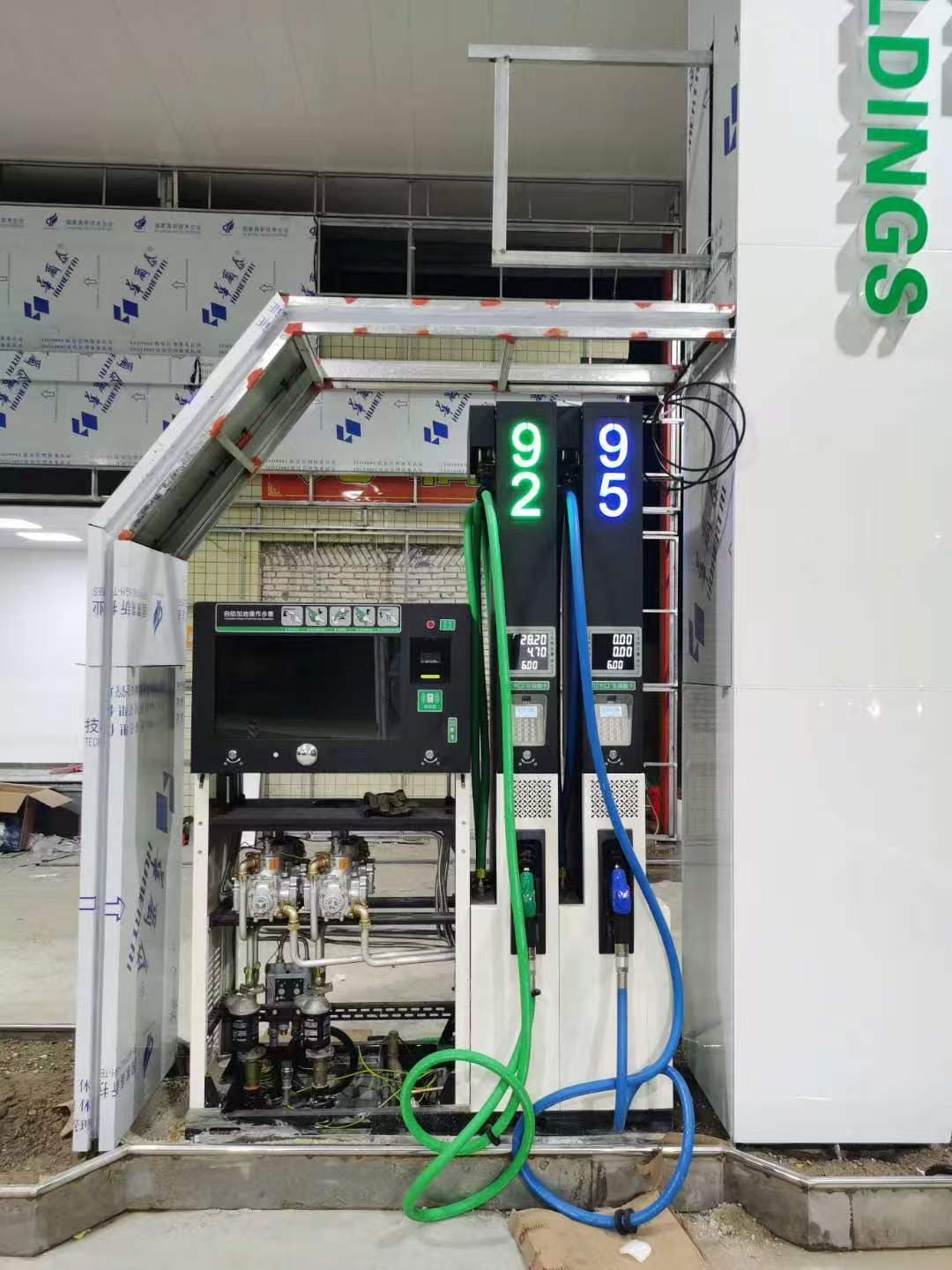
2. Confirm the Fuel Dispenser Before Installation
Before the dispenser is delivered to the site, confirm:
- Model
- Number of nozzles
- Fuel types
- Fuel grades
- Flow rate
- Product inlet size
- Vapor recovery connection
- Electrical voltage
- Phase
- Frequency
- Communication interface
- Safety components
- Required certifications
This information should match the approved project design.
3. Underground Fuel Piping Connection
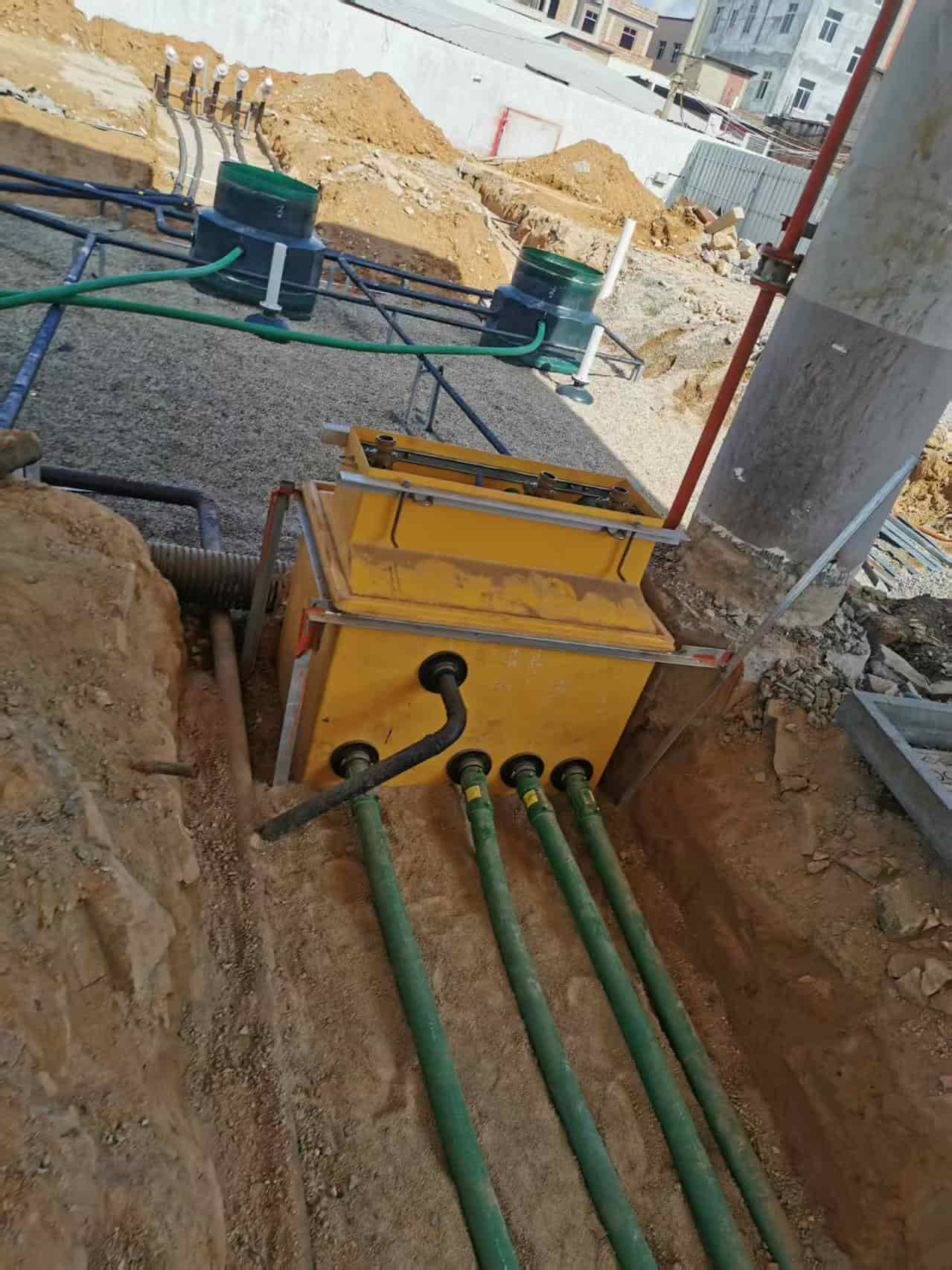
The product piping connects the underground storage system with the fuel dispenser.
The piping installation should consider:
- Pipe material
- Pipe diameter
- Routing
- Connection method
- Support
- Pressure testing
- Leak testing
- Secondary containment requirements
- Fuel compatibility
The pipeline should be properly connected to the pump system and dispenser inlet.
For a detailed explanation of underground piping design, see:
Gas Station Underground Fuel Piping
This creates a natural internal link between the system design article and the piping installation article.
4. Connecting a Fuel Dispenser to the Product Piping
The basic connection can be understood as:
Underground Tank
↓
Submersible Pump
↓
Product Piping
↓
Safety / Isolation Device
↓
Fuel Dispenser
The connection method also depends on whether the station uses a submersible pump or suction pump system. See our guide to submersible pump vs. suction pump systems for a detailed comparison.
For pressure-fed systems, a shear valve may be installed in the supply connection below the dispenser where required by the applicable design.
All pipe connections should be inspected before the system is put into operation.
5. Fuel Dispenser Installation
The dispenser should be positioned and secured according to the manufacturer’s installation requirements.
The installation team should check:
- Dispenser position
- Base and anchoring
- Vertical alignment
- Product inlet
- Electrical connection
- Communication connection
- Grounding
- Vapor recovery connection
- Emergency shut-off connection
The dispenser should be stable and correctly aligned before the hydraulic and electrical systems are connected.
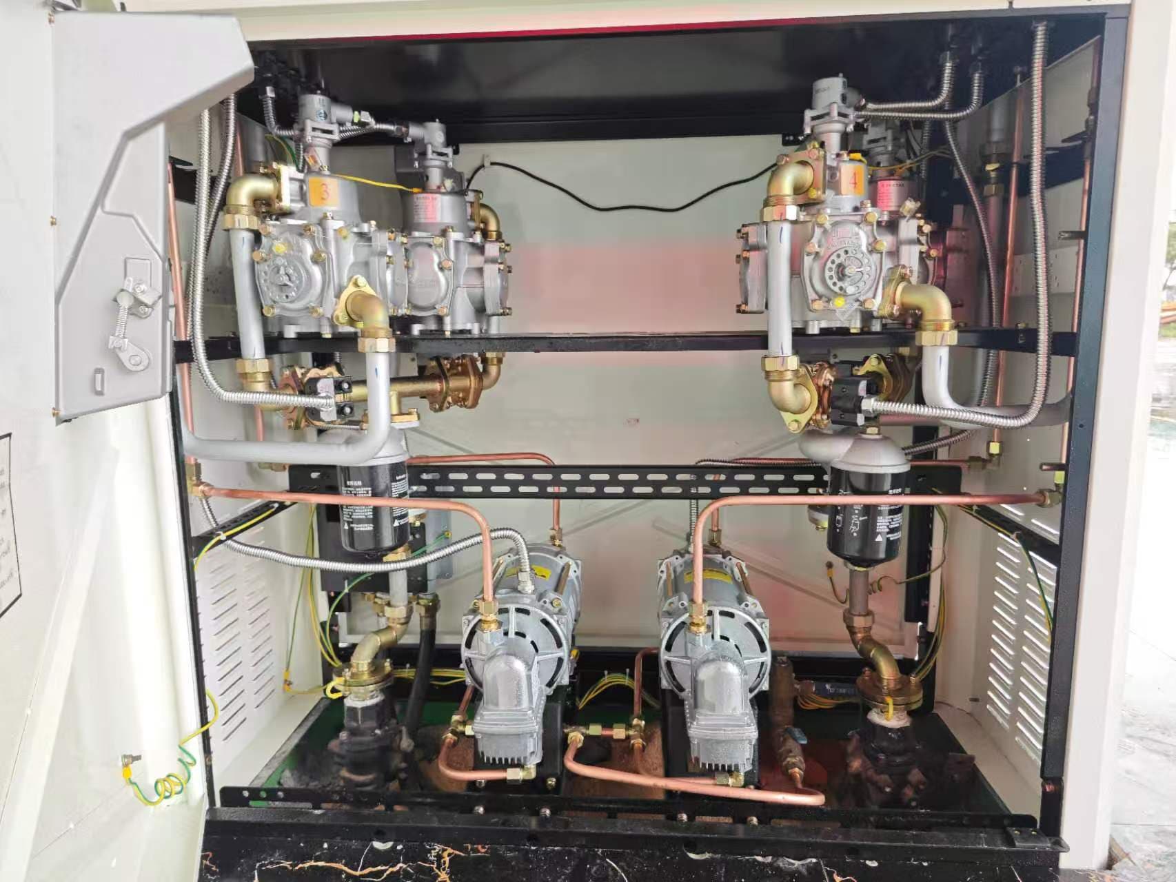
6. Electrical Installation
Electrical installation is a critical part of fuel dispenser commissioning.
Before connection, confirm:
- Voltage
- Phase
- Frequency
- Motor power
- Control circuit
- Communication wiring
- Grounding
- Emergency stop circuit
Do not assume that all fuel dispensers use the same electrical configuration.
The actual requirements must be taken from the selected dispenser model and the local electrical system.
7. Grounding and Static Protection
Fuel stations require appropriate grounding and bonding because fuel dispensing can involve flammable liquids and potentially hazardous vapors.
The installation should consider:
- Dispenser grounding
- Tank grounding
- Pipeline bonding where required
- Electrical equipment grounding
- Static protection
- Lightning protection
- Grounding continuity
The grounding system should be tested after installation according to the applicable project requirements.
8. Emergency Shut-Off System
The emergency shut-off system should be connected and tested before commissioning.
Depending on the system design, emergency shut-off may interact with:
- Fuel dispensers
- Submersible pumps
- Control systems
- Emergency stop buttons
The objective is to allow fuel dispensing to be stopped quickly when an emergency occurs.
The exact control logic and installation arrangement should follow the applicable regulations and equipment design.
9. Shear Valve Installation
For pressure-fed fuel dispensing systems, a shear valve may be installed at the dispenser supply connection where required.
The valve is intended to help isolate the fuel supply under specified emergency conditions such as severe dispenser impact or fire.
Its location, connection, alignment, and installation method are important.
The shear valve should not be treated as an optional decorative accessory. It is part of the safety design of the fuel delivery connection.
10. Hose, Swivel, Breakaway and Nozzle Installation
The final fuel delivery path normally includes:
Dispenser → Hose → Swivel → Breakaway → Nozzle
Each component has a different function.
Hose
Transfers fuel from the dispenser to the nozzle.
Swivel
Allows controlled rotation of the hose/nozzle assembly and helps reduce hose twisting.
Breakaway
Helps reduce uncontrolled fuel release if the vehicle moves away while the nozzle remains connected.
Nozzle
Provides the final connection to the vehicle fuel tank and controls fuel dispensing.
All components should be compatible with:
- Fuel type
- Flow rate
- Working pressure
- Connection size
- Installation configuration
- Applicable certification requirements
11. Vapor Recovery Connection
Where vapor recovery is required, the vapor recovery system must be coordinated with the dispenser installation.
The installation may include:
- Vapor recovery nozzle
- Vapor recovery hose
- Vapor piping
- Vapor valve
- Tank vapor connection
- Recovery equipment
The installer should confirm that the dispenser, vapor piping, tank and recovery equipment are compatible.
Incorrect vapor recovery connections can affect system performance and may create problems during commissioning.
12. Fuel Dispenser Commissioning
After installation, the system should be commissioned before normal operation.
Commissioning can generally be divided into four stages.
12.1 Hydraulic Testing
Check:
- Pump operation
- Fuel flow
- Pressure
- Connections
- Leakage
- Individual fueling positions
The actual dispensing performance should also be checked against the required fuel dispenser flow rate.
12.2 Metering Testing
Check:
- Flow meter
- Pulser signal
- Displayed quantity
- Metering performance
- Repeatability
- Calibration where required
Any legal metrology testing or calibration should follow the requirements applicable to the project location.
12.3 Electrical Testing
Check:
- Supply voltage
- Phase
- Frequency
- Wiring
- Grounding
- Communication
- Emergency stop
12.4 Safety Testing
Test the required safety functions, including:
- Emergency shut-off
- Shear valve arrangement
- Breakaway
- Grounding continuity
- Vapor recovery
- Required fire protection equipment
- Explosion-protected equipment installation
Need Technical Support for Fuel Dispenser Commissioning?
If you are preparing to install or commission fuel dispensers, Xing Zhong Yuan Energy can provide equipment configuration review, connection information, technical documentation, commissioning guidance, troubleshooting support, and spare parts support.
Send us your dispenser model, project requirements, and installation conditions to discuss your technical requirements.
13. Fuel Dispenser System Commissioning Checklist
Before handing the system over to the customer, check:
Equipment
- Correct dispenser model
- Correct nozzle configuration
- Correct fuel type
- Correct flow rate
Hydraulic System
- Pump operating correctly
- Product piping connected
- No visible leakage
- Required pressure/flow verified
Electrical System
- Correct voltage
- Correct phase
- Grounding completed
- Communication working
Safety System
- Emergency stop working
- Safety valves installed correctly
- Breakaway installed
- Required grounding completed
Metering
- Flow meter operating
- Display functioning
- Pulse signal functioning
- Required accuracy testing completed
Documentation
- Equipment manuals
- Wiring diagrams
- Test records
- Calibration records where required
- Maintenance information
14. Common Fuel Dispenser Installation Problems
Problem 1: Low Fuel Flow
Possible causes include:
- Pump capacity
- Pipeline restriction
- Blocked filter
- Valve problem
- Incorrect pipe configuration
- Pump operating conditions
Do not immediately assume the dispenser itself is defective.
The complete fuel delivery path should be checked.
Problem 2: Fuel Dispenser Does Not Dispense Fuel
Possible causes include:
- Power supply problem
- Emergency stop activated
- Pump not operating
- Solenoid valve problem
- Control board problem
- Communication or control signal problem
Troubleshooting should start from the system and move toward the individual component.
Problem 3: Fuel Leakage
Check:
- Hose
- Nozzle
- Swivel
- Breakaway
- Pipe connection
- Seals
- Fittings
The equipment should not be operated until the source of leakage has been identified and corrected.
Problem 4: Incorrect Metering
Possible causes include:
- Flow meter
- Pulser
- Calibration
- Electrical signal
- Mechanical components
- Fuel flow conditions
Metering problems should be investigated using the applicable testing and calibration procedure.
15. New Installation vs. Gas Station Renovation
Installation is usually more straightforward for a new station because the entire system can be designed together.
Renovation projects are different.
Existing:
- Tanks
- Piping
- Pumps
- Electrical wiring
- Dispensers
- Vapor recovery
- Communication systems
may need to be retained.
Therefore, before replacing an old dispenser, confirm the compatibility of the existing infrastructure.
A professional supplier can help review:
Existing System → Required New Configuration → Compatibility → Modification → Installation
before equipment production.
16. How We Support Fuel Dispenser System Installation
For overseas projects, installation support may include:
- Equipment configuration review
- Technical drawings
- Connection information
- Installation instructions
- Wiring information
- Product piping interface confirmation
- Commissioning guidance
- Troubleshooting support
- Spare parts support
For customers who already have site drawings, equipment lists, or technical specifications, these documents can be reviewed before equipment production to reduce installation problems.
17. FAQ
How do you install a fuel dispenser?
A fuel dispenser is installed by connecting it to the product piping, electrical supply, grounding, control system, safety devices, and vapor recovery system where applicable. The exact procedure depends on the dispenser model and project requirements.
What should be checked before installing a fuel dispenser?
Check the tank, pump, product piping, dispenser configuration, electrical supply, grounding, communication, vapor recovery, safety equipment, and installation space.
Does a fuel dispenser need grounding?
Fuel station electrical and grounding requirements depend on the applicable standards and equipment design. Proper grounding and bonding should be completed and tested according to the project requirements.
How do you test a fuel dispenser after installation?
Typical commissioning includes hydraulic testing, metering testing, electrical testing, communication testing, emergency shut-off testing, and other required safety checks.
Can an old fuel dispenser be replaced without replacing the underground system?
Sometimes, but it depends on the compatibility of the existing tank, piping, pump, electrical system, vapor recovery, and the new dispenser.
A compatibility assessment should be completed before replacement.
18. Final Recommendation
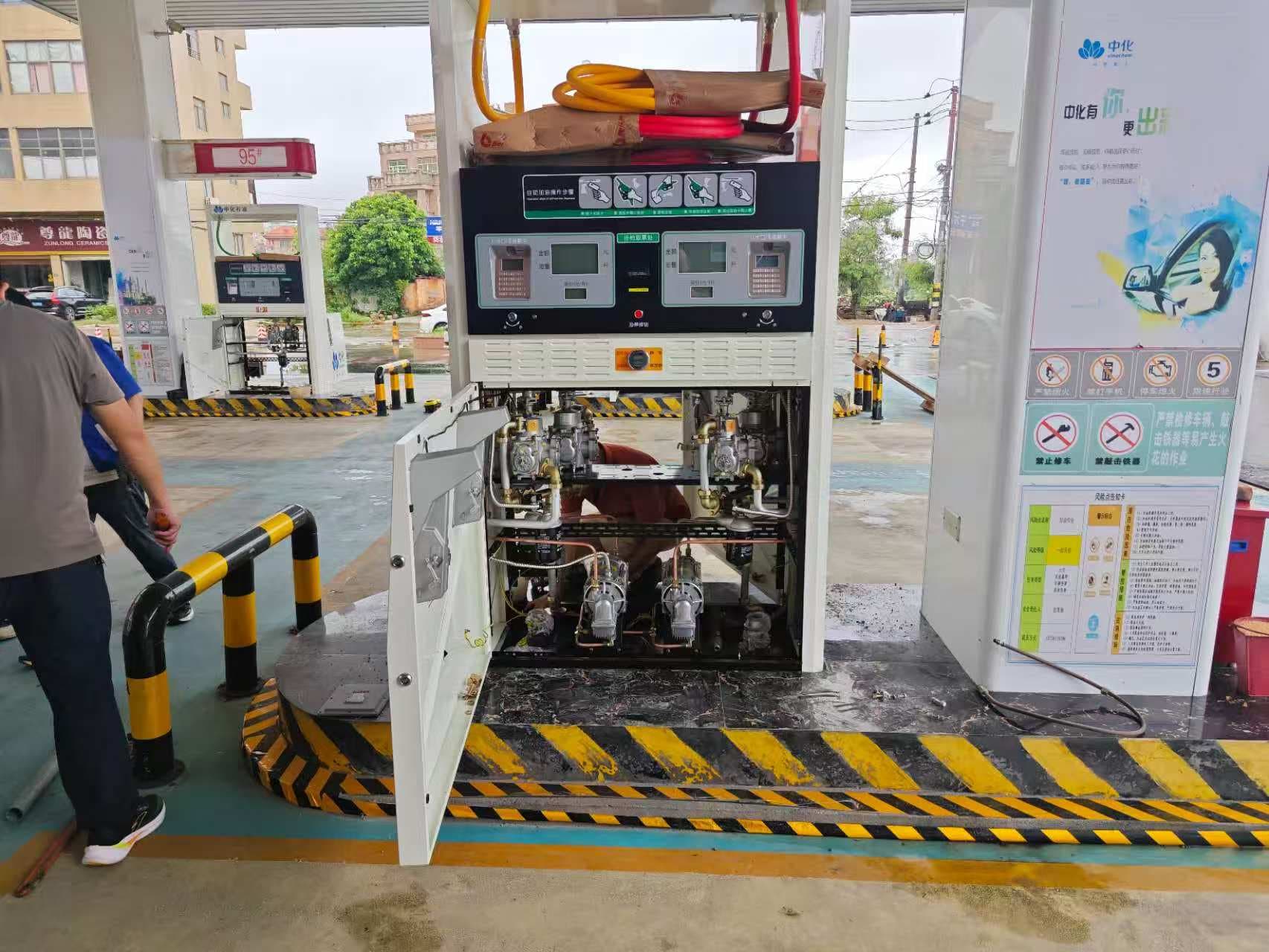
A successful fuel dispenser installation depends on more than placing the dispenser on the fueling island.
The complete connection should be properly coordinated:
Tank → Pump → Product Piping → Safety Device → Dispenser → Meter → Valve → Hose → Nozzle
At the same time, the electrical, grounding, communication, vapor recovery, emergency shut-off, and other required safety systems must be correctly integrated.
Before installation, confirm the complete equipment configuration and interfaces.
During installation, follow the equipment manufacturer’s instructions and applicable local requirements.
After installation, complete hydraulic, electrical, metering, communication, and safety testing before putting the system into normal operation.
Xing Zhong Yuan Energy supports overseas customers with fuel dispenser equipment selection, customized configurations, technical coordination, installation guidance, spare parts, and after-sales support.
Send us your project requirements to get a customized fuel dispenser system installation and equipment solution.